
Angle adjusting piece for steel support

An angle adjustment, steel support technology, applied in excavation, construction, infrastructure engineering, etc., can solve problems such as unable to provide support, irregular shape of foundation pit, etc., to achieve flexible angle adjustment, wide application range, and improved stability.

Pending Publication Date: 2021-04-30
DONGTONG ROCK SOIL SCI & TECH HANGZHOU
View PDF4 Cites 0 Cited by
  • Summary
  • Abstract
  • Description
  • Claims
  • Application Information

AI Technical Summary

Problems solved by technology

The triangular piece is usually an isosceles right triangle, which can provide good support for the case where the two sides of the foundation pit supported by the two ends of the steel support beam are at 90 degrees, but cannot provide good support for the two sides of the foundation pit to be supported at other angles. good support
However, in actual construction, the shape of the foundation pit is often very irregular, and only relying on regular long steel support beams and existing triangular pieces for angle adjustment can no longer meet the needs of actual construction

Method used


Image

  • Angle adjusting piece for steel support
  • Angle adjusting piece for steel support
  • Angle adjusting piece for steel support

Examples


Embodiment 1

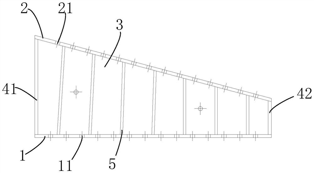
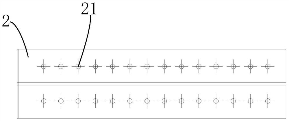
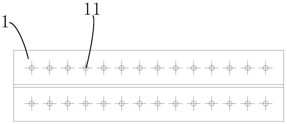
[0031] Please refer to Figure 1 to Figure 6 As shown, it is a diagram of Embodiment 1 of an angle adjustment member for steel support in the present application. The angle adjusting member for steel support includes a bottom flange plate 1, a top flange plate 2 and a web 3, and the bottom flange plate 1, the top flange plate 2 and the web 3 are all steel plates. The bottom flange plate 1 and the top flange plate 2 are opposite to each other, and the web 3 intersects the bottom flange plate 1 and the top flange plate 2 . That is, the web 3 is erected between the bottom flange 1 and the top flange 2 . Preferably, the lower and upper ends of the web 3 are connected to the central axis of the length direction of the bottom flange 1 and the top flange 2, so that the angle adjustment member has a symmetrical structure, ensuring Force balance during use. The web 3 is perpendicular to the bottom flange 1 and the top flange 2 .

[0032] see Figure 4 As shown, the web 3 is a righ...

Embodiment 2

[0037] see Figure 7 As shown, it is a diagram of Embodiment 2 of an angle adjustment member for steel support in the present application. It differs from Embodiment 1 mainly in that the included angle it forms is different from Embodiment 1. In this embodiment, the angle between the top flange plate 2 and the bottom flange plate 1 of the angle adjusting member is 5°. Each component and its structure in this embodiment can be set with reference to Embodiment 1, and will not be repeated here. In another embodiment, the angle formed by the top flange plate 2 and the bottom flange plate 1 of the angle adjusting member may also be 10° or other angles.

Embodiment 3

[0039] see Figure 8 and Figure 9 As shown, it is a diagram of Embodiment 3 of an angle adjustment member for steel support in the present application. The main difference between it and Embodiment 1 and Embodiment 2 is that it also includes an adapter plate 6 .

[0040] Specifically, in this embodiment, the angle adjusting member for steel support further includes an adapter plate 6 . The adapter plate 6 is parallel to the bottom flange plate 1 and welded on the web 3 , and the stiffening plate 5 includes a joint welded between the adapter plate 6 and the bottom flange plate 1 The first stiffening plate 51 between them, and the second stiffening plate 52 welded between the adapter plate 6 and the top flange plate 2 . The first stiffening plate 51 is perpendicular to the bottom flange plate 1 , the adapter plate 6 and the web 3 respectively. The second stiffening plate 52 is perpendicular to the top flange plate 2 and the web 3 , but not perpendicular to the adapter plate...


PUM


Abstract

The invention provides an angle adjusting piece for a steel support. The angle adjusting piece comprises a web, a bottom end flange plate, a top end flange plate, a first end plate, a second end plate and a plurality of stiffening plates, wherein, the web is in a right trapezoid shape and comprises a first side end, a second side end, a bottom end and a top end, the length of the first side end is larger than that of the second side end, and an included angle of 5 degrees-30 degrees is formed between the extension line of the top end and the extension line of the bottom end; the bottom end flange plate is vertically welded to the bottom end of the web, and the top end flange plate is vertically welded to the top end of the web; and the stiffening plates are arranged on the two sides of the web, the stiffening plates located on the same side of the web are arranged side by side in the direction from the first side end to the second side end of the web, the heights of the stiffening plates are sequentially reduced, each stiffening plate is welded to the bottom end flange plate, the top end flange plate and the web at the same time, and the stiffening plates are perpendicular to the web and the bottom end flange plate. The angle adjusting piece is flexible in angle adjustment, and can meet the supporting requirements of foundation pits in irregular shapes.

Description

technical field [0001] The present application relates to the technical field of construction engineering, in particular to an angle adjusting member for steel supports. Background technique [0002] In order to maintain the safety of the foundation pit, it is necessary to set up a support system around the foundation pit to reinforce and support the foundation pit. The steel support beam is the main component of the foundation pit support system, and the steel support beam has a pair of brace arrangement and a corner brace arrangement in the foundation pit. For the angle brace arrangement, the steel support beam and the two sides of the foundation pit supported by its two ends are not vertically arranged, so triangular pieces are often required. The triangular piece is usually an isosceles right triangle, which can provide good support for the case where the two sides of the foundation pit supported by the two ends of the steel support beam are at 90 degrees, but cannot pr...

Claims


Application Information

Patent Timeline
Patent Type & Authority Applications(China)
IPC IPC(8): E02D17/04
CPCE02D17/04
Inventor 黄星迪胡琦徐晓兵黄天明方华建王涛朱海娣竹相邓以亮李健平娄泽峰
Owner DONGTONG ROCK SOIL SCI & TECH HANGZHOU
Learn More