Lighting control device and lighting control method for vehicle lamp, and vehicle lamp system

A lighting control, vehicle technology, applied in the direction of headlights, vehicle parts, signal devices, etc., can solve the problem of violation, increase the lateral movement toward the outside, etc.

Pending Publication Date: 2022-05-10
STANLEY ELECTRIC CO LTD
View PDF1 Cites 0 Cited by
  • Summary
  • Abstract
  • Description
  • Claims
  • Application Information

AI Technical Summary

Problems solved by technology

[0003] However, in the vehicular lamps that perform sequential turn instructions as described above, people who visually recognize the vehicular lamps (for example, pedestrians, drivers of other vehicles, etc.) increase the recognition of lateral movement from the inside of the vehicle toward the outside. such a load
Therefore, compared with the conventional type of turn signal that simply blinks repeatedly, the turn signal that performs sequential turn indication may bring a sense of incongruity as a light for direction indication.

Method used


Image

  • Lighting control device and lighting control method for vehicle lamp, and vehicle lamp system
  • Lighting control device and lighting control method for vehicle lamp, and vehicle lamp system
  • Lighting control device and lighting control method for vehicle lamp, and vehicle lamp system

Examples


Embodiment Construction

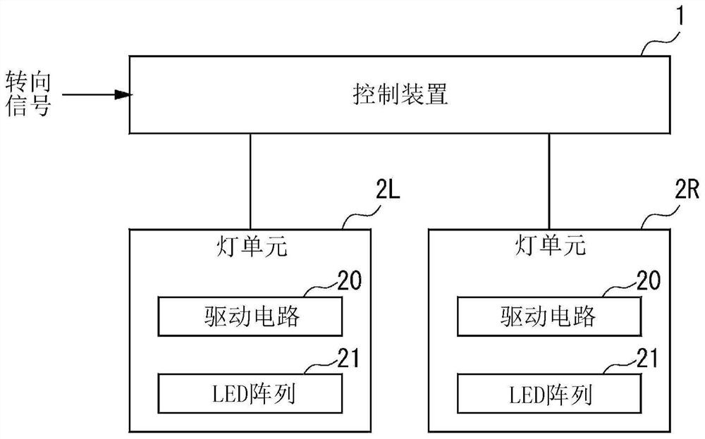
[0026] figure 1 It is a block diagram showing the configuration of a vehicle lighting system according to one embodiment. The illustrated vehicle lamp system is used as a blinker (turn signal), for example, and is configured to include a control device 1 and a pair of lamp units (vehicle lamps) 2L, 2R whose operations are controlled by the control device 1 .

[0027] When a turn signal indicating that the direction indicator is operated is input from the vehicle, the control device 1 controls the lighting state of either of the lamp units 2L, 2R according to the turn signal, and emits light indicating the traveling direction of the vehicle.

[0028] The pair of lamp units 2L and 2R each include a drive circuit 20 and an LED array 21 . The lamp unit 2L is provided on the left side of the vehicle front. The lamp unit 2R is provided on the right side of the vehicle front. In addition, a pair of lamp units may be provided on the left and right sides of the vehicle rear in the s...


PUM


Abstract

The purpose of the present invention is to reduce the feeling of discomfort when performing a sequential turn instruction. A lighting control device for a vehicle lamp is used for controlling lighting of the vehicle lamp, and the lighting control device carries out the following control: flickering a light emitting area of the vehicle lamp at a first brightness; during the lighting of the light-emitting region, either one or more bright spots formed by causing a partial region of the light-emitting region to have a second luminance higher than the first luminance, or one or more dark spots formed by causing a partial region of the light-emitting region to have a second luminance higher than the first luminance, are moved within the light-emitting region. The one or more dark spots are formed by causing a partial region of the first light-emitting region to have a third brightness lower than the first brightness.

Description

technical field [0001] The present invention relates to, for example, a vehicle lighting system used as a turn signal (winker). Background technique [0002] As one type of winkers used in vehicles, there is known a winker in which a plurality of light emitting units are sequentially turned on with a time difference (for example, refer to Patent Document 1). Here, such a lighting method is called sequential turn indication. A vehicle lamp that performs such a sequential turn instruction is, for example, controlled to repeat an operation in which each light emitting unit is turned on sequentially from the inside toward the outside of the vehicle, and then all the light emitting units are simultaneously turned off. [0003] However, in the vehicular lamps that perform sequential turn instructions as described above, people who visually recognize the vehicular lamps (for example, pedestrians, drivers of other vehicles, etc.) increase the recognition of lateral movement from th...

Claims


Application Information

Patent Timeline
Patent Type & Authority Applications(China)
IPC IPC(8): B60Q1/34
CPCB60Q1/346B60Q1/381B60Q2900/40Y02B20/40F21S41/663
Inventor 中岛航喜多靖木村能子工藤功基熊仓晓久冈田英隆大山修斗
Owner STANLEY ELECTRIC CO LTD
Why Eureka
Try Eureka