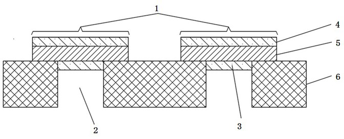
Fabrication Process of Flexible Lead Frames Avoiding Blind Via Plating
A technology of flexible lead and preparation process, which is applied in the fields of printed circuit manufacturing, circuit, printed circuit, etc., can solve problems such as the difficulty in electroplating of flexible lead frame pressure welding holes, achieve the goal of increasing the electroplating rate, solving the problem of missed plating, and improving product quality Effect
- Summary
- Abstract
- Description
- Claims
- Application Information
AI Technical Summary
Problems solved by technology
Method used
Image
Examples
Embodiment 1
[0048] The flexible lead frame is prepared by the process of the present invention, and the process flow is:
[0049] (1) First conduct electroplating on the back of the conductive metal layer:
[0050] ①Press dry film for the first time: Use film pressing equipment to stick photosensitive film on the upper and lower surfaces of the conductive metal layer. The pressing parameters of the photosensitive film are temperature 90℃, pressure 0.1Mpa, speed 1m / min.
[0051] ②The first exposure: Use exposure equipment to expose the position of the non-pressure welding hole on the photosensitive film. The exposure light source is 5000W ultraviolet parallel light, and the exposure light intensity is 10mw / cm 2 , the exposure time is 10s.
[0052] ③The first development: Use a developing device with a spray function, use a weak alkaline chemical solution (sodium carbonate), remove the unexposed photosensitive film, and leak the position corresponding to the pressure welding hole, that is,...
Embodiment 2
[0070] The flexible lead frame is prepared by the process of the present invention, and the process flow is:
[0071] (1) First conduct electroplating on the back of the conductive metal layer:
[0072] ①The first time to dry the film: use the film pressing equipment to stick the photosensitive film on the upper and lower surfaces of the conductive metal layer. The pressing parameters of the photosensitive film are the temperature of 100℃, the pressure of 0.3Mpa, and the speed of 3m / min.
[0073] ②The first exposure: Use exposure equipment to expose the position of the non-pressure welding hole on the photosensitive film. The exposure light source is 5000W ultraviolet parallel light, and the exposure light intensity is 30mw / cm 2 , the exposure time is 5s.
[0074] ③The first development: Use a developing device with a spray function, use a weak alkaline chemical solution (sodium carbonate), remove the unexposed photosensitive film, and leak the position corresponding to the p...
Embodiment 3
[0092] The flexible lead frame is prepared by the process of the present invention, and the process flow is:
[0093] (1) First conduct electroplating on the back of the conductive metal layer:
[0094] ①Press dry film for the first time: Use film pressing equipment to stick photosensitive film on the upper and lower surfaces of the conductive metal layer. The pressing parameters of the photosensitive film are temperature 110℃, pressure 0.5Mpa, speed 5m / min.
[0095] ②The first exposure: Use exposure equipment to expose the position of the non-pressure welding hole on the photosensitive film. The exposure light source is 5000W ultraviolet parallel light, and the exposure light intensity is 50mw / cm 2 , the exposure time is 1s.
[0096] ③The first development: Use a developing device with a spray function, use a weak alkaline chemical solution (sodium carbonate), remove the unexposed photosensitive film, and leak the position corresponding to the pressure welding hole, that is,...
PUM
| Property | Measurement | Unit |
|---|---|---|
| depth | aaaaa | aaaaa |
Abstract
Description
Claims
Application Information
 - R&D
- Intellectual Property
- Life Sciences
- Materials
- Tech Scout
- Unparalleled Data Quality
- Higher Quality Content
- 60% Fewer Hallucinations
Browse by: Latest US Patents, China's latest patents, Technical Efficacy Thesaurus, Application Domain, Technology Topic, Popular Technical Reports.
© 2025 PatSnap. All rights reserved.Legal|Privacy policy|Modern Slavery Act Transparency Statement|Sitemap|About US| Contact US: help@patsnap.com

