Eureka AIR delivers breakthrough ideas for toughest innovation challenges, trusted by R&D personnel around the world.

A kind of anti-interference method, equipment and medium of diffuse reflection photoelectric sensor

A photoelectric sensor and diffuse reflection technology, which is applied in the field of intelligent sensors, can solve the problems of affecting the signal frequency of the through-beam photoelectric sensor, reducing the working accuracy and efficiency, and low working efficiency, so as to reduce the design complexity and improve the working accuracy and efficiency, the effect of improving work efficiency

Active Publication Date: 2022-06-21
天津宜科自动化股份有限公司
View PDF27 Cites 0 Cited by
  • Summary
  • Abstract
  • Description
  • Claims
  • Application Information

AI Technical Summary

Problems solved by technology

[0004] (1) It is necessary to set the signal frequency of each diffuse reflection photoelectric sensor to avoid mutual interference of signal frequencies, but it will lead to complicated calculation and debugging, and low work efficiency;
[0005] (2) When the detection time slice difference of two adjacent diffuse reflection photoelectric sensors affects the signal frequency difference of two adjacent through-beam photoelectric sensors, so that the signal frequencies of the two diffuse reflection photoelectric sensors are mutually When disturbed, the accuracy and efficiency of the work will be reduced

Method used


Image

  • A kind of anti-interference method, equipment and medium of diffuse reflection photoelectric sensor
  • A kind of anti-interference method, equipment and medium of diffuse reflection photoelectric sensor

Examples


Embodiment 1

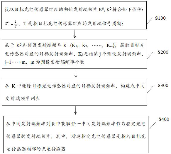
[0023] like figure 1 As shown, the first embodiment provides an anti-interference method for a diffuse reflection photoelectric sensor, and the method includes the following steps:

[0024] S100, obtain the initial transmitter frequency K corresponding to the target photoelectric sensor 0 , K 0 Meet the following conditions:

[0025] , T refers to the signal period of the transmitting end corresponding to the target photoelectric sensor; the signal period of the transmitting end corresponding to the target photoelectric sensor is the period of the light signal emitted by the transmitting end in any target photoelectric sensor.

[0026] Specifically, the target photoelectric sensor refers to any one of n photoelectric sensors, each photoelectric sensor is a diffuse reflection photoelectric sensor, and the diffuse reflection photoelectric sensor at least includes: a transmitting end and a receiving end located on the same side, and a detection circuit , wherein the transmit...

Embodiment 2

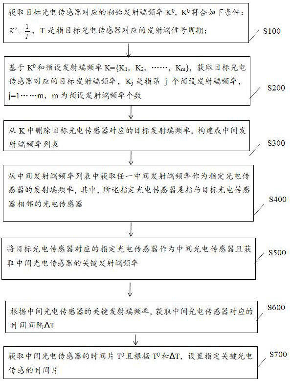
[0059] like figure 2 As shown, the second embodiment provides an anti-interference method for a diffuse reflection photoelectric sensor, the method further includes the following steps in addition to S100-S400:

[0060] S500, take the designated photoelectric sensor corresponding to the target photoelectric sensor as the intermediate photoelectric sensor and obtain the key transmitting end frequency of the intermediate photoelectric sensor; it can be understood as: the key transmitting end frequency of the designated photoelectric sensor is the key transmitting end frequency of the intermediate photoelectric sensor.

[0061] S600. Obtain the time interval ΔT corresponding to the intermediate photoelectric sensor according to the key transmitter frequency of the intermediate photoelectric sensor, where ΔT meets the following conditions:

[0062] , where S is a preset parameter, and T' is the time period corresponding to the intermediate photoelectric sensor.

[0063] Specif...


PUM


Abstract

The present invention provides a diffuse reflection photoelectric sensor anti-jamming method, equipment and medium. The method includes: the target sensor obtains the frequency of the transmitting end of the adjacent photoelectric sensor, and according to the frequency of the transmitting end of the adjacent photoelectric sensor, the target photoelectric sensor sets The frequency of the transmitting end of itself makes it inconsistent with the frequency of the transmitting end of the adjacent photoelectric sensor; it can be seen that the present invention can control the frequency of the transmitting end of the photoelectric sensor to work at different frequencies, and can avoid the abnormal frequency of the transmitting end of the photoelectric sensor, resulting in signal frequency Mutual interference, improve work accuracy and efficiency.

Description

technical field [0001] The invention relates to the technical field of intelligent sensors, in particular to an anti-interference method, equipment and medium of a diffuse reflection photoelectric sensor. Background technique [0002] At present, in many scenarios, photoelectric sensors often control the installation distance to avoid mutual interference of multiple photoelectric sensors. [0003] In the prior art, the diffuse reflection photoelectric sensor is an optoelectronic product with the transmitter and the receiver on the same side. It mainly uses light as the medium to receive and convert the light between the light-emitting body and the light-receiving body. The diffuse reflection photoelectric sensors use different signal frequencies to avoid mutual interference, but there are the following problems: [0004] (1) It is necessary to set the signal frequency of each diffuse reflection photoelectric sensor to avoid mutual interference of signal frequencies, but it ...

Claims


Application Information

Patent Timeline
Patent Type & Authority Patents(China)
IPC IPC(8): G01D3/036G01S7/48
CPCG01D3/036G01S7/48
Inventor 代红林高鹏
Owner 天津宜科自动化股份有限公司
Why Eureka
Eureka Blog
Learn More