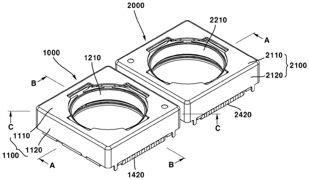
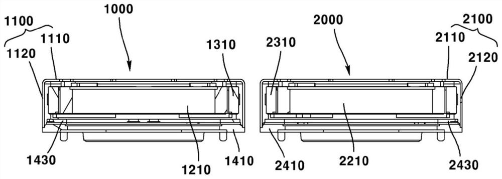
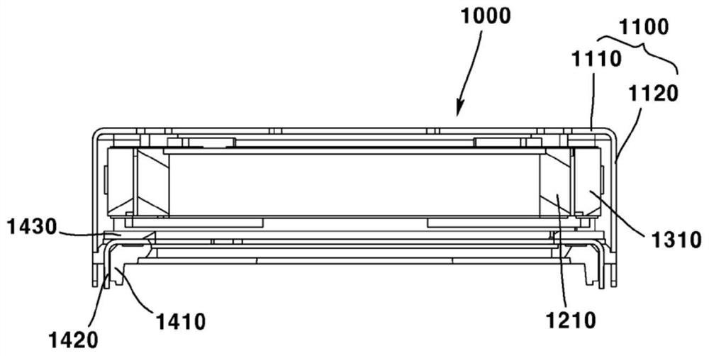
Camera module

A camera module and a corresponding technology, which are applied to cameras, camera bodies, and printing devices, etc., can solve the problems of camera module magnetic field interference, narrow camera module gaps, and drive linearity deterioration, and achieve the effect of minimizing size.

Pending Publication Date: 2022-05-17
LG INNOTEK CO LTD
View PDF8 Cites 0 Cited by
  • Summary
  • Abstract
  • Description
  • Claims
  • Application Information

AI Technical Summary

Problems solved by technology

However, in the prior art dual camera module, since the gap between the camera modules is narrow, there is a problem that there is magnetic field interference between the camera modules
However, recently, with the increase in lens size and weight and the increase in the travel range of lens movement, the electromagnetic force for autofocus drive has become insufficient during design, and drive linearity has deteriorated

Method used


Image

  • Camera module
  • Camera module
  • Camera module

Examples


Embodiment Construction

[0105] Hereinafter, preferred embodiments of the present invention will be described in detail with reference to the accompanying drawings.

[0106] However, the technical idea of ​​the present invention is not limited to some embodiments to be described, but may be implemented in various forms, and within the scope of the technical idea of ​​the present invention, one or more of the constituent elements may be The various embodiments are selectively combined or replaced.

[0107] In addition, unless clearly defined and described, the terms (including technical terms and scientific terms) used in the various embodiments of the present invention can be interpreted as meanings that can be commonly understood by those skilled in the art, and commonly used terms such as Terms defined in dictionaries may be interpreted in consideration of meanings in the context of related technologies.

[0108] In addition, the terms used in this specification are for describing the embodiments a...


PUM


Abstract

The present embodiment relates to a camera module including a first camera module including first to third magnets disposed at first to third corners of a first cover and a first dummy member disposed at a fourth corner of the first cover, and a second camera module including second to third magnets disposed at second to fourth corners of the first cover. And the second camera module includes fourth to sixth magnets disposed at fifth to seventh corners of the second cover, and a second dummy member disposed at an eighth corner of the second cover, in which the first dummy member is adjacent to the sixth magnet of the fourth to sixth magnets, and the second dummy member is adjacent to a third magnet of the first to third magnets.

Description

technical field [0001] This embodiment relates to a camera module. Background technique [0002] With the wide spread of various portable terminals and the commercialization of wireless Internet services, consumer demands related to the portable terminals are also diversifying, so that various types of additional devices are installed in the portable terminals. [0003] Among the various types of attachment devices, there is a camera module that takes a photo or video of an object as a representative one. Meanwhile, recently, a dual camera module in which two camera modules are arranged side by side has been researched. However, in the prior art dual camera module, since the gap between the camera modules is narrow, there is a problem that there is magnetic field interference between the camera modules. [0004] In addition, an autofocus function that automatically adjusts the focus according to the distance of the object is being applied to the camera module. However, re...

Claims


Application Information

Patent Timeline
Patent Type & Authority Applications(China)
IPC IPC(8): G02B7/09G03B13/36G03B17/12H04N5/225
CPCG02B7/09G03B17/12G03B13/36H04N23/54H04N23/55G03B5/00G03B30/00G03B2205/0069H04N23/45H04N23/51H04N23/57H04N23/687
Inventor 金中喆张玹准吴柾锡
Owner LG INNOTEK CO LTD
Why Eureka
Try Eureka