
Mount bushing

a technology for mounting bushings and vehicles, applied in the direction of vehicle sub-unit features, shock absorbers, jet propulsion mountings, etc., can solve the problems of adversely affecting vehicle noise, vibration, harshness, etc., and achieve the effect of preventing noise, vibration, and harshness

Pending Publication Date: 2022-09-08
DTR AUTOMOTIVE CORP
View PDF0 Cites 0 Cited by
  • Summary
  • Abstract
  • Description
  • Claims
  • Application Information

AI Technical Summary

Benefits of technology

The present disclosure aims to provide a mount bushing that can minimize noise, vibration, and harshness by reducing shifting of frequency caused by a mass of the mount bushing. The mount bushing includes an outer tube, an inner tube, a rubber part, a tubular mass, and a stopper. The mass and the stopper are separated from each other as much as possible, which prevents peak frequency from varying when an external load changes. This results in a mount bushing that can maintain constant peak frequency, thereby preventing noise, vibration, and harshness from occurring.

Problems solved by technology

Specifically, in driving of an electric vehicle, as a Z-directional load is input to a mount by engine torque in response to a step degree of an accelerator, dynamic properties are also changed, and frequency of a first resonance around 500 Hz caused by the mass is shifted backward and the dynamic properties are also amplified, so that there is a problem in that the frequency shifting adversely affects vehicle noise, vibration, and harshness.

Method used


Image

  • Mount bushing
  • Mount bushing
  • Mount bushing

Examples


Embodiment Construction

[0024]Hereinbelow, an embodiment of the present disclosure will be described in detail with reference to accompanying drawings. The contents described hereinbelow and with reference to the accompanying drawings is presented for a general understanding of the present disclosure. The technical scope of the present disclosure is not limited thereto. Detailed descriptions of known functions and configurations which are deemed to make the gist of the present disclosure obscure will be omitted

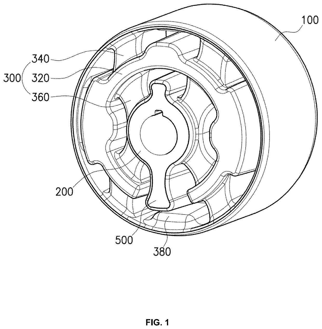
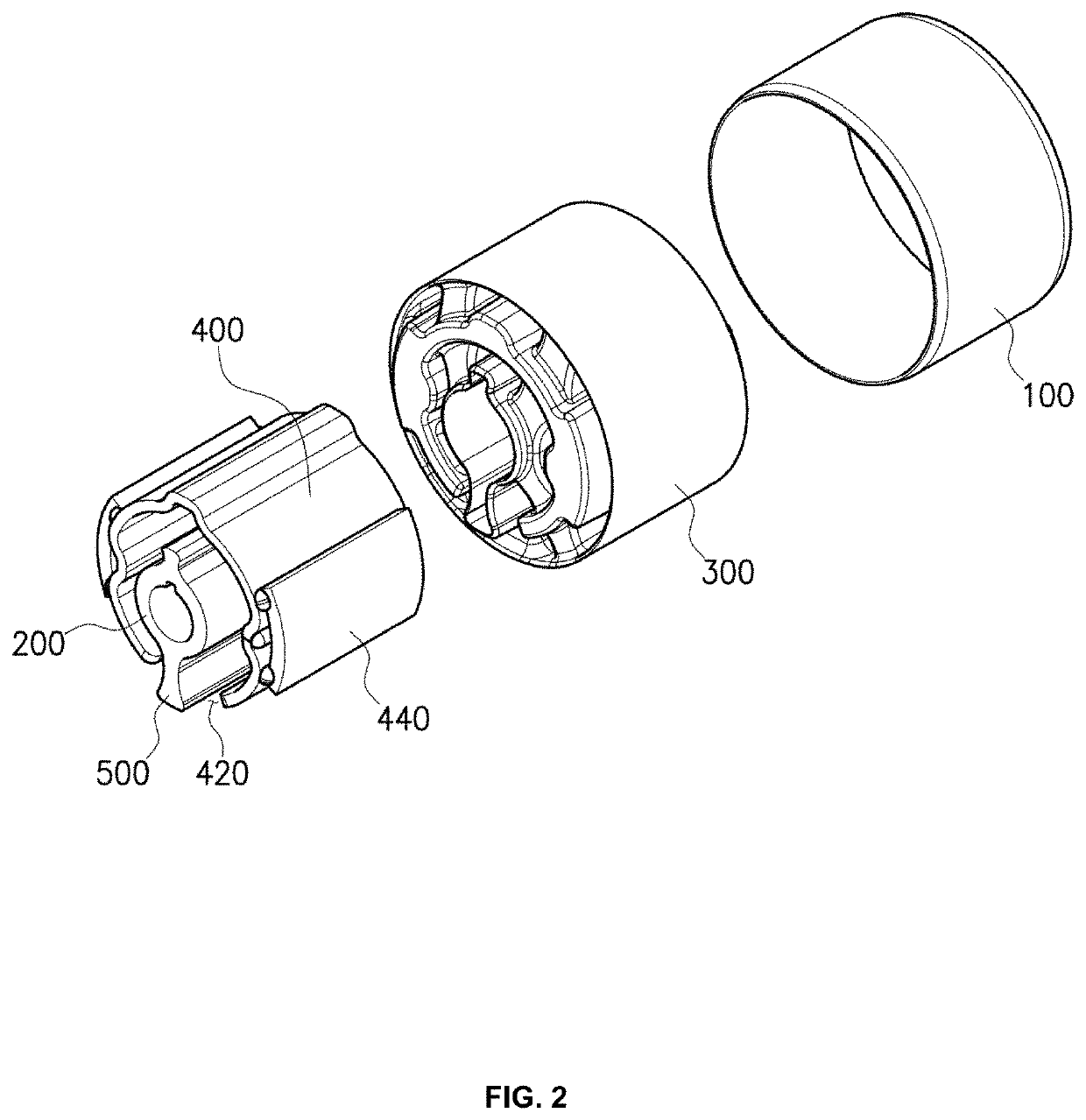
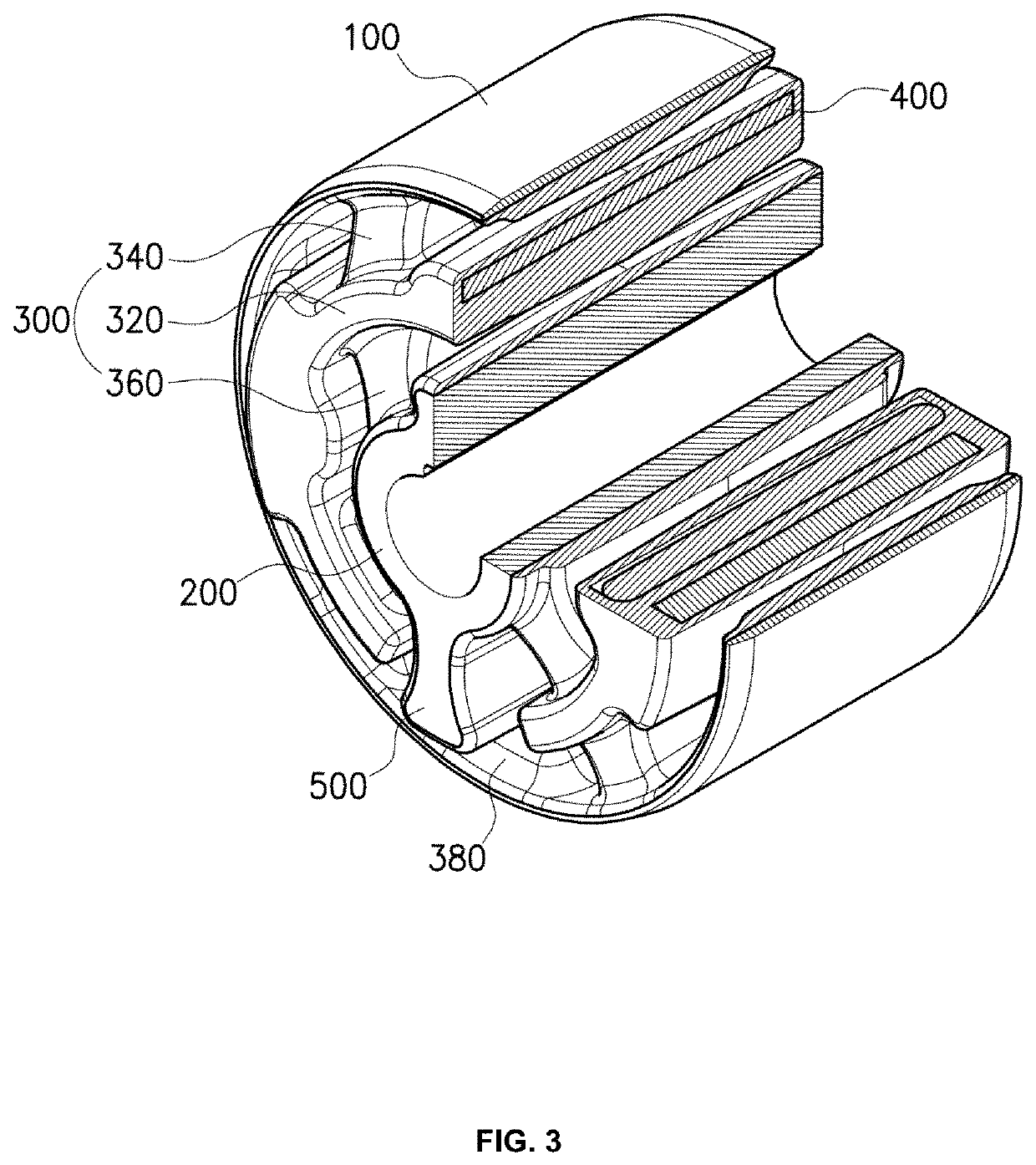
[0025]FIG. 1 is a perspective view showing a mount bushing according to an embodiment of the present disclosure. FIG. 2 is an exploded-perspective view showing the mount bushing according to the embodiment of the present disclosure. FIG. 3 is an inner structure view showing the mount bushing according to the embodiment of the present disclosure. FIG. 4 is a front view showing the mount bushing according to the embodiment of the present disclosure. FIG. 5 is a view showing an example of a mass of the ...


PUM


Abstract

A mount bushing is proposed. The mount bushing is configured to minimize frequency shifting according to difference of dynamic properties applied by a load input to a mount. The mount bushing includes an outer tube, an inner tube provided in the outer tube, a rubber part provided between the outer tube and the inner tube, a tubular mass provided in the rubber part and having an opening formed by partially penetrating an outer circumferential surface thereof, and a stopper shaped to protrude outward from the inner tube to pass through the opening of the tubular mass, wherein the mount bushing is configured to minimize mutual interference between the mass and the stopper in deformation due to an external force.

Description

REFERENCE TO RELATED APPLICATIONS[0001]This application claims the priority benefit of Korean Patent Application No. 10-2021-0030260 filed on Mar. 8, 2021, the entire contents of which are incorporated herein by reference.FIELD OF THE INVENTION[0002]The present disclosure relates generally to a mount bushing for a vehicle and, more particularly, to a mount bushing configured to minimize frequency shifting according to difference of dynamic properties applied by a load input to a mount.BACKGROUND OF THE INVENTION[0003]A mount bushing is used in a vehicle, and generally, has an outer tube, an inner tube, and a rubber part provided between the outer tube and the inner tube, and a mass is provided in the rubber part to reinforce the rigidity of the mount bushing.[0004]Specifically, in driving of an electric vehicle, as a Z-directional load is input to a mount by engine torque in response to a step degree of an accelerator, dynamic properties are also changed, and frequency of a first re...

Claims


Application Information

Patent Timeline
Patent Type & Authority Applications(United States)
IPC IPC(8): B60G21/055F16C17/10
CPCB60G21/0551F16C17/10B60G2204/1222B60G2204/41F16F1/371F16F1/3828F16F1/3863F16F7/108B60K5/1208B60K5/1291B60Y2306/09B60Y2200/91
Inventor JO, WOO SEONJANG, SUK DONGYOO, DONG HYEON
Owner DTR AUTOMOTIVE CORP
Learn More