Mobile terminal and method of operating antenna thereof

a mobile terminal and antenna technology, applied in the direction of resonant antennas, polarisation/directional diversity, electromagnetic wave modulation, etc., can solve the problems of deteriorating reception performance, mutual interference phenomenon, and deteriorating reception performance, so as to minimize mutual interference and improve wireless communication performance

Active Publication Date: 2014-12-16
SAMSUNG ELECTRONICS CO LTD
View PDF9 Cites 0 Cited by
  • Summary
  • Abstract
  • Description
  • Claims
  • Application Information

AI Technical Summary

Benefits of technology

[0007]To address the above-discussed deficiencies of the prior art, it is a primary object to provide a mobile terminal and a method of operating an antenna thereof that can improve a wireless communication performance by minimizing mutual interference between a plurality of antennas.
[0008]The present invention further provides a mobile terminal and a method of operating an antenna thereof that can reduce mutual interference between a plurality of antennas in a mobile terminal that include a diversity antenna using the plurality of antennas.

Problems solved by technology

When the antennas have a similar resonance frequency, a mutual interference phenomenon may occur.
Furthermore, as mobile communication technology develops, a data transmitting speed remarkably increases, and thus a fading phenomenon occurs, thereby deteriorating a reception performance.
The fading phenomenon is a phenomenon in which a reception performance is deteriorated because a receiving electric field is not constant due to multi-path noise of transmitted electric waves.
In a small-sized mobile terminal, a limitation exists in securing a physical distance between antennas for forming a diversity antenna.
In a conventional mobile terminal, when a plurality of antennas that use the same or similar frequency band are mounted, a wireless communication performance of the mobile terminal may be deteriorated due to mutual interference between antennas.

Method used


Image

  • Mobile terminal and method of operating antenna thereof
  • Mobile terminal and method of operating antenna thereof
  • Mobile terminal and method of operating antenna thereof

Examples


Embodiment Construction

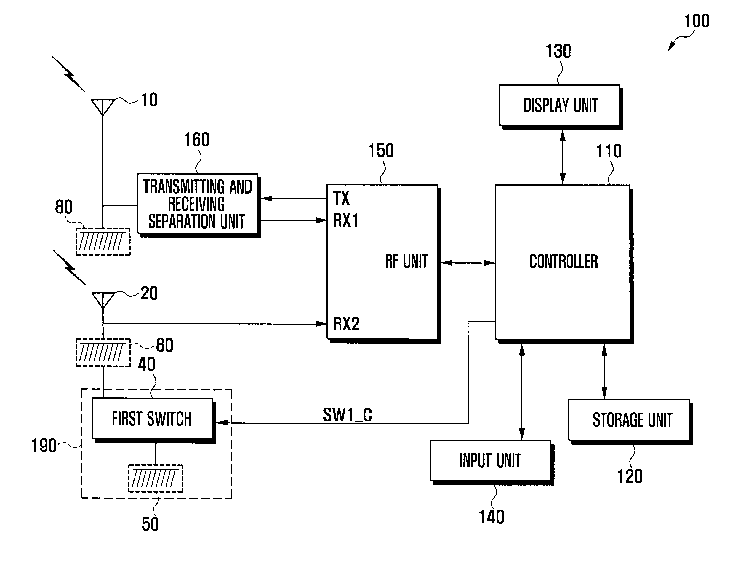
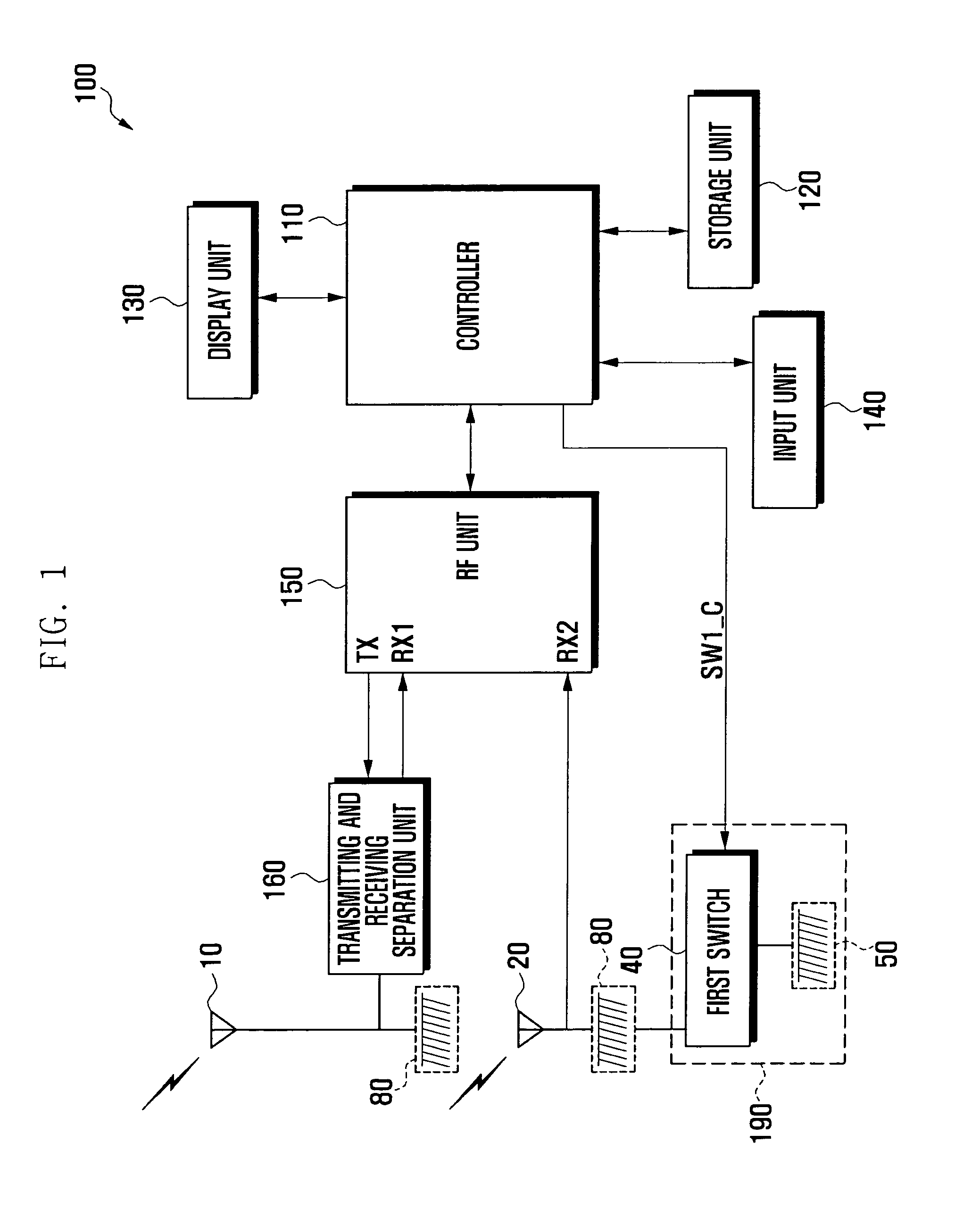
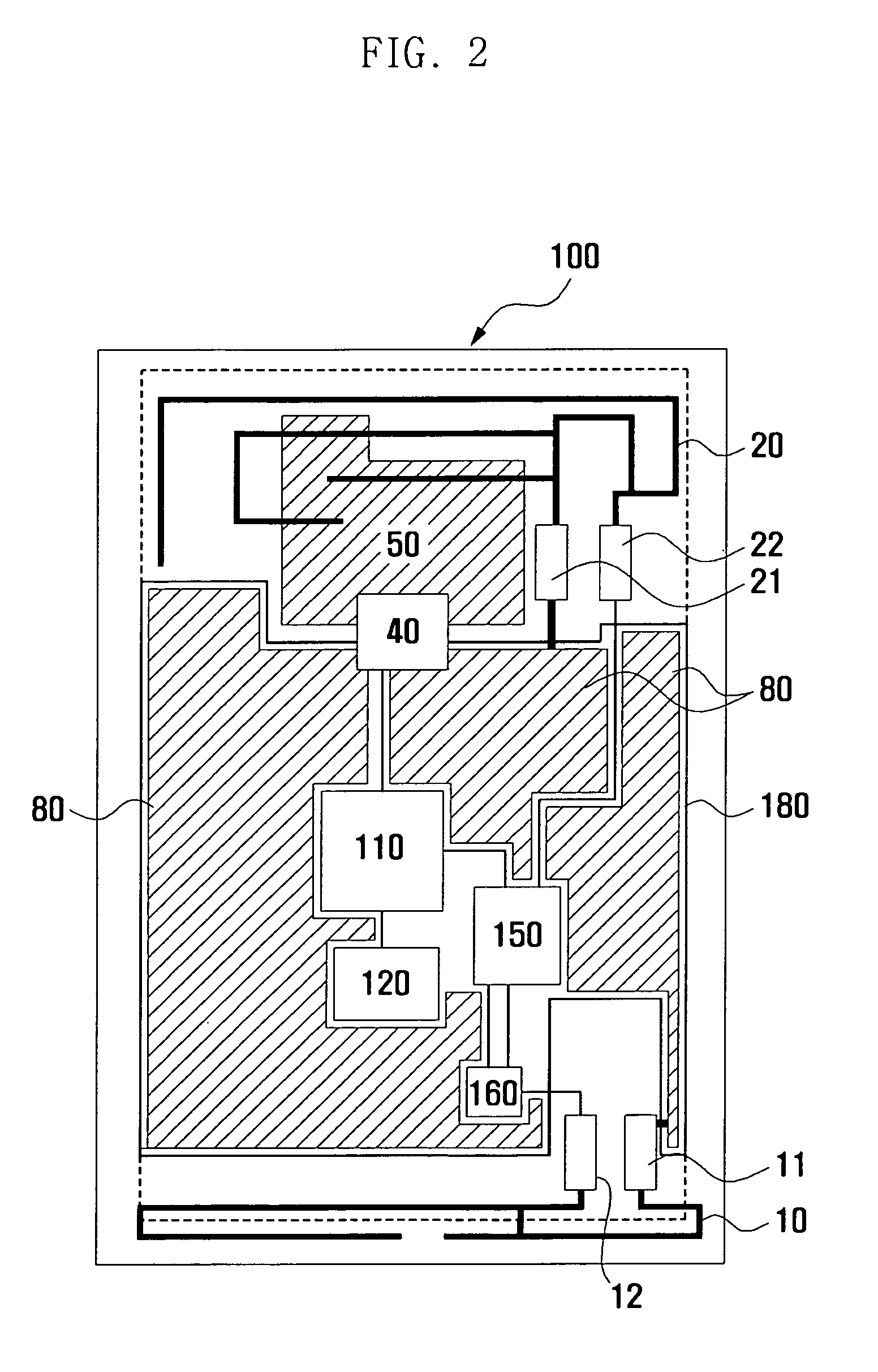
[0019]FIGS. 1 through 6, discussed below, and the various embodiments used to describe the principles of the present disclosure in this patent document are by way of illustration only and should not be construed in any way to limit the scope of the disclosure.

[0020]Those skilled in the art will understand that the principles of the present disclosure may be implemented in any suitably arranged wireless communication device. The views in the drawings are schematic views only, and are not intended to be to scale or correctly proportioned. Detailed descriptions of well-known functions and structures incorporated herein may be omitted to avoid obscuring the subject matter of the present invention.

[0021]While the present invention may be embodied in many different forms, specific embodiments of the present invention are shown in drawings and are described in detail, with the understanding that the present disclosure is to be considered as an exemplification of the principles of the inven...


PUM


Abstract

A mobile terminal and a method of operating an antenna thereof are provided. The mobile terminal includes a plurality of antennas.A resonance frequency moving unit moves a resonance frequency of at least one of the plurality of antennas. And a controller controls the resonance frequency moving unit to sustain or move a resonance frequency of the at least one antenna according to use of a plurality of antennas. Therefore, by minimizing mutual interference occurring between a plurality of antennas using a similar frequency band, a wireless communication performance can be improved.

Description

CROSS-REFERENCE TO RELATED APPLICATION(S) AND CLAIM OF PRIORITY[0001]The present application is related to and claims priority under 35 U.S.C. §119 to an application filed in the Korean Intellectual Property Office on Dec. 7, 2009 and allocated Serial No. 10-2009-0120360, the contents of which are incorporated herein by reference.TECHNICAL FIELD OF THE INVENTION[0002]The present invention relates to a mobile terminal and a method of operating an antenna thereof and, more particularly, to a mobile terminal and a method of operating an antenna thereof that can minimize a mutual interference phenomenon between a plurality of antennas in a mobile terminal that include the plurality of antennas.BACKGROUND OF THE INVENTION[0003]Nowadays, with rapid technology development, mobile terminals provide various additional functions such as text message transmitting and receiving functions, image photographing function, music reproduction function, digital broadcasting service function, E-mail se...

Claims


Application Information

Patent Timeline
Patent Type & Authority Patents(United States)
IPC IPC(8): H04B7/06H01Q9/14H04B7/10H04B7/08H01Q21/28H01Q1/24H04B7/12H04M1/00
CPCH04B7/0693H04B7/0825H01Q1/243H04B7/0691H01Q21/28H04B7/12H04B7/10H01Q9/14
Inventor SEO, SUNG, IN
Owner SAMSUNG ELECTRONICS CO LTD
Why Eureka
Try Eureka