Laser cutting device for steel plate

A laser cutting and steel plate technology, applied in laser welding equipment, metal processing equipment, welding equipment, etc., can solve the problems of cutting to the roller and affecting the normal operation of the equipment

Pending Publication Date: 2022-05-24
GUANGZHOU CHANGREN IND TECH CO LTD
View PDF5 Cites 0 Cited by
  • Summary
  • Abstract
  • Description
  • Claims
  • Application Information

AI Technical Summary

Problems solved by technology

Therefore, there is a problem that the roller may be cut in the prior art, which affects the normal operation of the equipment

Method used


Image

  • Laser cutting device for steel plate
  • Laser cutting device for steel plate
  • Laser cutting device for steel plate

Examples


Embodiment Construction

[0047] In the description of this application, it should be understood that the terms "center", "portrait", "horizontal", "top", "bottom", "front", "rear", "left", "right", " The orientations or positional relationships indicated by vertical, horizontal, top, bottom, inner, and outer are based on the orientations or positional relationships shown in the accompanying drawings, and are only for the convenience of describing the present application and The description is simplified rather than indicating or implying that the device or element referred to must have a particular orientation, be constructed and operate in a particular orientation, and therefore should not be construed as limiting the application. In the description of this application, unless stated otherwise, "plurality" means two or more.

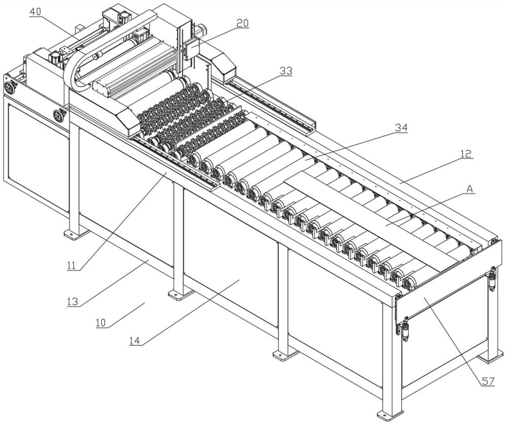
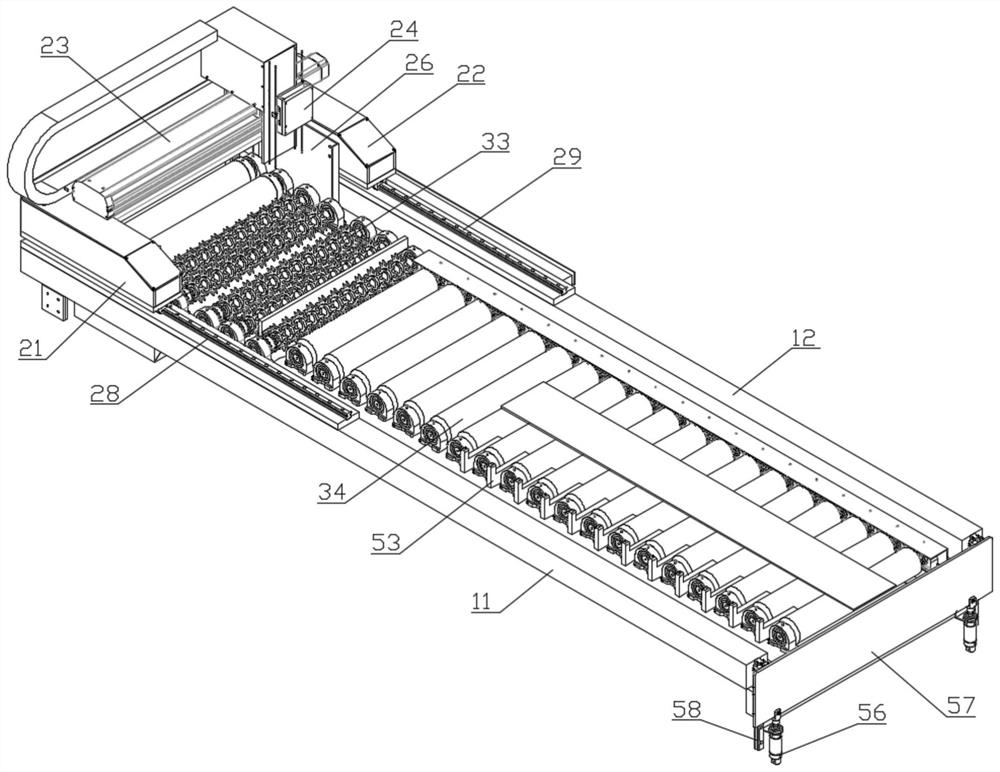
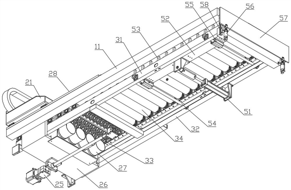
[0048] see Figure 1-Figure 8 , an exemplary laser cutting device for steel plates of the present application includes a support frame 10, a laser cutting mechanism 20 and a c...


PUM


Abstract

The invention relates to a laser cutting device for a steel plate. The laser cutting device for the steel plate comprises a supporting frame, a laser cutting mechanism and a conveying mechanism. The laser cutting mechanism and the conveying mechanism are installed on the supporting frame, and the laser cutting mechanism is placed above the conveying mechanism. The conveying mechanism comprises a first conveying frame rod, a second conveying frame rod, a gear conveying assembly, a roller conveying assembly and a synchronous driving assembly. The gear conveying assembly comprises a supporting gear, a wheel shaft and a bearing seat. The laser cutting mechanism comprises a first mounting seat, a second mounting seat, a transverse driving assembly and a laser cutting head; the laser cutting head is arranged above the gear conveying assembly; and the first mounting seat and the second mounting seat are respectively connected with the supporting frame. The laser cutting device for the steel plate has the advantages of preventing laser from puncturing conveying equipment so as to ensure the safety and long-term use of the conveying equipment.

Description

technical field [0001] The present application relates to the technical field of steel plate cutting, and in particular, to a laser cutting device for steel plates. Background technique [0002] When the existing steel plate is cut, the steel plate is laid on the conveyor belt, and the steel plate is cut by the transverse movement of the laser. Conveyor belts are usually roller conveyor belts, and when laser cutting, it is usually cut in the gap between two rollers. Since the steel plate is in contact with the roller, if the laser hits the roller during cutting, the roller will be broken down. When working for a long time, the rollers need to be replaced regularly to ensure the normal use of the equipment. Therefore, in the prior art, there is a problem that the roller may be cut, which affects the normal operation of the equipment. SUMMARY OF THE INVENTION [0003] Based on this, the purpose of the present application is to provide a laser cutting device for steel plat...

Claims


Application Information

Patent Timeline
Patent Type & Authority Applications(China)
IPC IPC(8): B23K26/38B23K26/70
CPCB23K26/38B23K26/702Y02P70/10
Inventor 姚宇茏
Owner GUANGZHOU CHANGREN IND TECH CO LTD
Why Eureka
Try Eureka