Fixing and placing device for electromechanical equipment

A technology for electromechanical equipment and storage boxes, which is applied in the direction of mechanical equipment, electrical equipment shells/cabinets/drawers, electrical components, etc., can solve problems such as damage to electromechanical equipment, and achieve the effect of convenient shockproof and shock absorption

Active Publication Date: 2022-05-27
国网浙江省电力有限公司杭州市富阳区供电公司
View PDF13 Cites 2 Cited by
  • Summary
  • Abstract
  • Description
  • Claims
  • Application Information

AI Technical Summary

Problems solved by technology

Although this device prevents the bottom of the electromechanical equipment from being corroded due to moisture, when the electromechanical equipment is in use, when the vibration is large, if there is no good shock absorption, it will cause damage to the interior of the electromechanical equipment

Method used


Image

  • Fixing and placing device for electromechanical equipment
  • Fixing and placing device for electromechanical equipment
  • Fixing and placing device for electromechanical equipment

Examples


Embodiment 1

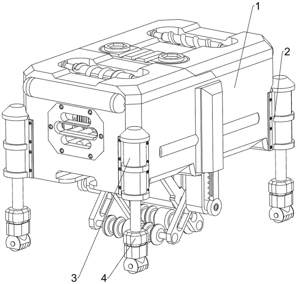
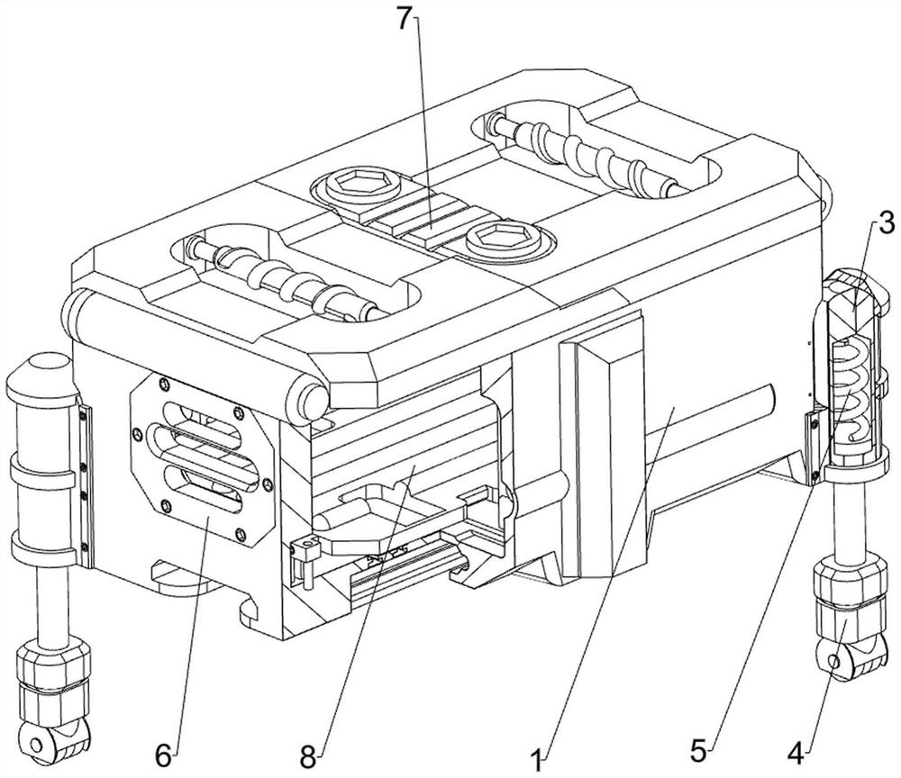
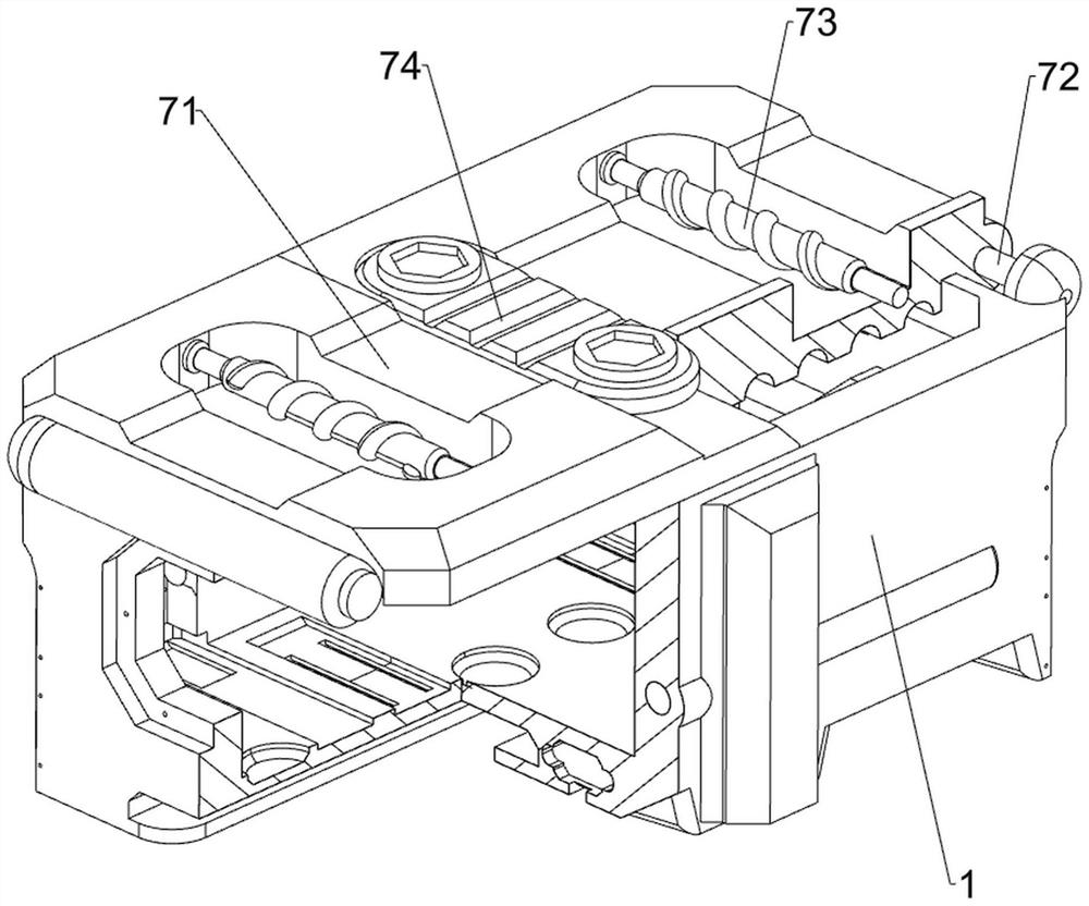
[0037] A fixed placement device for electromechanical equipment, such as Figure 1-Figure 5 As shown, it includes a fixed placement box 1, a mounting frame 2, a fixed vertical cylinder 3, a support column 4, a support spring 5, an interface fixing plate 6, a sealing mechanism 7 and a buffer mechanism 8, and the lower part of the outer side of the fixed placement box 1 is spaced through bolts There are four mounting brackets 2 connected in a way, the mounting bracket 2 is fixed with a fixed vertical cylinder 3, the fixed vertical cylinder 3 is slidably provided with a supporting column 4, and a support is provided between the top of the supporting column 4 and the interior of the fixed vertical cylinder 3 Spring 5, an interface fixing plate 6 is embedded in the middle of the left part of the fixed placing box 1, a sealing mechanism 7 is arranged on the fixed placing box 1, the sealing mechanism 7 can realize sealing protection, and a buffer mechanism 8 is arranged in the fixed p...

Embodiment 2

[0042] On the basis of Example 1, as Figure 6-Figure 8 As shown, it also includes an anti-vibration mechanism 9, and the anti-vibration mechanism 9 includes a protective bottom cover 91, a first anti-vibration mount 92, a second anti-vibration mount 93, an auxiliary roller 94, a limit slider 95, a reset guide rod 96 and a reset spring 97. Three protective bottom covers 91 are connected at intervals in the middle of the outer bottom of the fixed placement box 1 by means of bolts. The lower parts of the three protective bottom covers 91 are hingedly provided with a first shock mount 92. There is a second shock mount 93, the first shock mount 92 and the second shock mount 93 are in an X-shaped state, because the triangle has stability, the fixed placement box 1 can be well shockproof, the first shock mount 92 and the second shock mount The lower part of 93 is rotatably provided with auxiliary rollers 94, and the left and right sides of the lower part of the fixed placement box 1...

Embodiment 3

[0049] On the basis of Example 1 and Example 2, as Figure 12 and Figure 15 As shown, it also includes a heat dissipation mechanism 12. The heat dissipation mechanism 12 includes a heat dissipation outer frame 121, a dust cover 122 and a cooling fan 123. The upper right side of the fixed placement box 1 is embedded with a heat dissipation outer frame 121. The front and rear sides are rotatably provided with cooling fans 123 , and the operation of the cooling fans 123 can realize heat dissipation for the electromechanical equipment. The left and right sides of the cooling outer frame 121 are symmetrically fixed with dust covers 122 in the front and rear.

[0050] When the electromechanical equipment is placed in the fixed placement box 1, people can start the cooling fan 123 to work, and the cooling fan 123 operates to dissipate heat from the electromechanical equipment. The dust cover 122 can prevent sundries or garbage from contacting the cooling fan 123, causing the cooling...


PUM


Abstract

The invention relates to a placing device, in particular to a fixed placing device for electromechanical equipment. According to the fixing and placing device for the electromechanical equipment, damping of the electromechanical equipment can be facilitated, and damage to the interior of the electromechanical equipment is avoided. A fixing and placing device for electromechanical equipment comprises a fixing and placing box, mounting frames, fixing vertical cylinders and supporting stand columns, the four mounting frames are connected to the lower portion of the outer side face of the fixing and placing box at intervals in a bolt mode, the fixing vertical cylinders are fixedly connected into the mounting frames, and the supporting stand columns are arranged in the fixing vertical cylinders in a sliding mode. According to the electromechanical equipment shock absorption device, the stress holding rod pulls the sealing bottom frame to swing outwards, then the electromechanical equipment is placed in the fixed placement box, the first buffer spring buffers the electromechanical equipment through the buffer rubber plate, and then the supporting stand column also plays a role in buffering the fixed placement box through the supporting spring, so that the electromechanical equipment can be conveniently damped, and the service life of the electromechanical equipment is prolonged. And the interior of the electromechanical equipment is not damaged.

Description

technical field [0001] The present invention relates to a placement device, in particular to a fixed placement device for electromechanical equipment. Background technique [0002] With the continuous improvement of people's living standards, people have more and more needs for electromechanical equipment in their daily life. From transportation to various household appliances, computers, printers, etc., they have become indispensable electromechanical products in people's lives. [0003] The professional application CN211525859U discloses a moisture-proof base for electromechanical equipment, belonging to the field of electromechanical equipment, including a mounting seat, a side baffle, a rubber gasket, a switch plate, a No. 2 gasket, a fixing nut, a mounting screw, an adjusting nut, an adjusting screw, Rotatable support structure, screw head. In the present invention, the electromechanical equipment can be placed in the rectangular structure enclosed by the side baffle t...

Claims


Application Information

Patent Timeline
Patent Type & Authority Applications(China)
IPC IPC(8): H05K7/14H05K5/02F16F15/08
CPCH05K7/14H05K5/0204F16F15/085Y02E60/10
Inventor 马怡娜
Owner 国网浙江省电力有限公司杭州市富阳区供电公司
Why Eureka
Try Eureka