
Antenna device and electronic equipment

An antenna device and radio wave technology, applied in the direction of antenna support/installation device, antenna equipment with additional functions, antenna, etc., can solve the problems of limiting the frequency band and performance of MIMO antennas

Pending Publication Date: 2022-06-03
HUAWEI TECH CO LTD
View PDF0 Cites 0 Cited by
  • Summary
  • Abstract
  • Description
  • Claims
  • Application Information

AI Technical Summary

Problems solved by technology

Therefore, the very limited space inside the electronic device limits the frequency band and performance that the MIMO antenna can cover

Method used


Image

  • Antenna device and electronic equipment
  • Antenna device and electronic equipment
  • Antenna device and electronic equipment

Examples


Embodiment Construction

[0049] Various exemplary embodiments, features and aspects of the present application will be described in detail below with reference to the accompanying drawings. The same reference numbers in the figures denote elements that have the same or similar functions. While various aspects of the embodiments are shown in the drawings, the drawings are not necessarily drawn to scale unless otherwise indicated.

[0050] The word "exemplary" is used exclusively herein to mean "serving as an example, embodiment, or illustration." Any embodiment described herein as "exemplary" is not necessarily to be construed as preferred or advantageous over other embodiments.

[0051] In addition, in order to better illustrate the present application, numerous specific details are given in the following detailed description. It should be understood by those skilled in the art that the present application may be practiced without certain specific details. In some instances, methods, means, compone...


PUM


Abstract

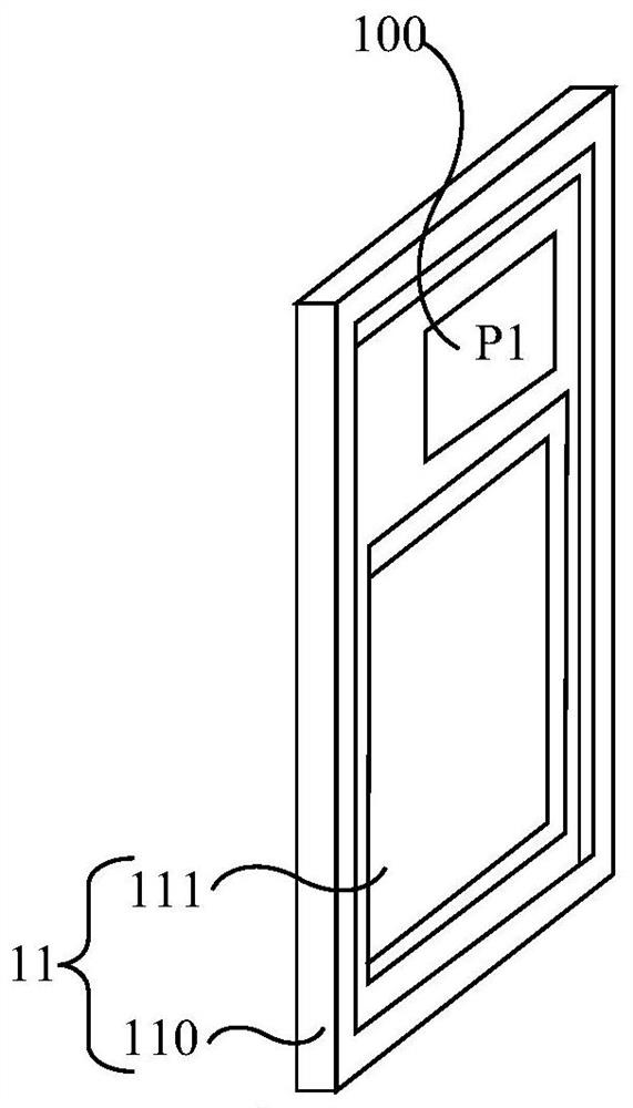
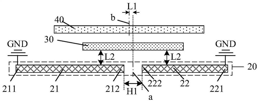
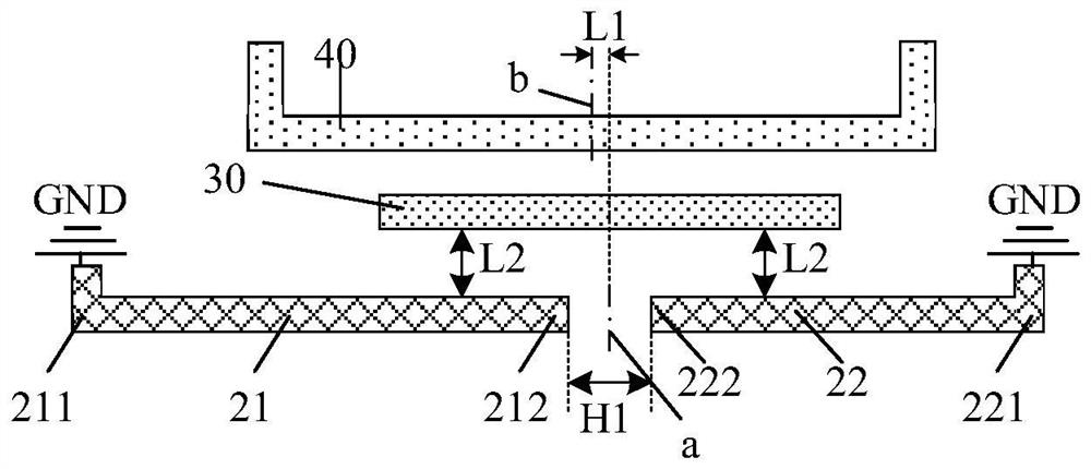
The invention relates to an antenna device and electronic equipment. The antenna device comprises a first branch knot, a frame branch knot and a second branch knot, the frame branch knot is provided with a first gap, and the frame branch knot is divided into a first frame branch knot and a second frame branch knot by the first gap; the first branch knot and the second branch knot are arranged according to an axial symmetry structure, the symmetry axis of the first branch knot coincides with the first center line of the first gap, the symmetry axis of the second branch knot is parallel to the first center line and has a first distance with the first center line, and the first center line is the center line, perpendicular to the length direction of the frame branch knot, of the first gap; the first end, away from the first gap, of the first frame branch is electrically connected with the reference ground. The first end, away from the first gap, of the second frame branch is electrically connected with the reference ground. According to the antenna device and the electronic equipment provided by the invention, same-frequency decoupling of the second frame branch knot and the second branch knot is realized.

Description

technical field [0001] The present application relates to the field of antenna technology, and in particular, to an antenna device and an electronic device. Background technique [0002] With the development of communication technology and electronic equipment, especially the advent of the fifth-generation mobile communication technology (5G) era, electronic equipment needs to support more antennas and frequency bands to achieve the high transmission rate required by 5G. For example, using multiple input multiple output (MIMO) technology on electronic equipment can effectively improve channel reliability through space diversity gain, reduce channel bit error rate, and finally achieve the purpose of increasing data rate. However, in a MIMO antenna structure, the number of antennas is proportional to the space occupied by the antennas. Therefore, the very limited space inside the electronic device limits the frequency band and performance that the MIMO antenna can cover. How...

Claims


Application Information

Patent Timeline
IPC IPC(8): H01Q5/28H01Q5/50H01Q1/22
CPCH01Q5/28H01Q5/50H01Q1/22H01Q9/42H01Q5/385H01Q5/35H01Q1/521H01Q21/28H01Q1/243H01Q9/0407
Inventor 余冬黄志军刘珂鑫赵方超黄鹏王汉阳
Owner HUAWEI TECH CO LTD
Learn More