
Particle inerter system based on sub-flow state contact stress network

A contact stress and network technology, applied in the field of particle inertial capacity systems, can solve the problems of large additional mass of particle dampers and low particle collision efficiency, and achieve the effects of intensifying energy dissipation, accelerating deconstruction, and improving robustness.

Pending Publication Date: 2022-06-17
TONGJI UNIV
View PDF0 Cites 0 Cited by
  • Summary
  • Abstract
  • Description
  • Claims
  • Application Information

AI Technical Summary

Problems solved by technology

[0005] The purpose of the present invention is to provide a particle inertial system based on the subfluid contact stress network in order t

Method used


Image

  • Particle inerter system based on sub-flow state contact stress network
  • Particle inerter system based on sub-flow state contact stress network
  • Particle inerter system based on sub-flow state contact stress network

Examples


Example Embodiment

[0031]下面结合附图和具体实施例对本发明进行详细说明。

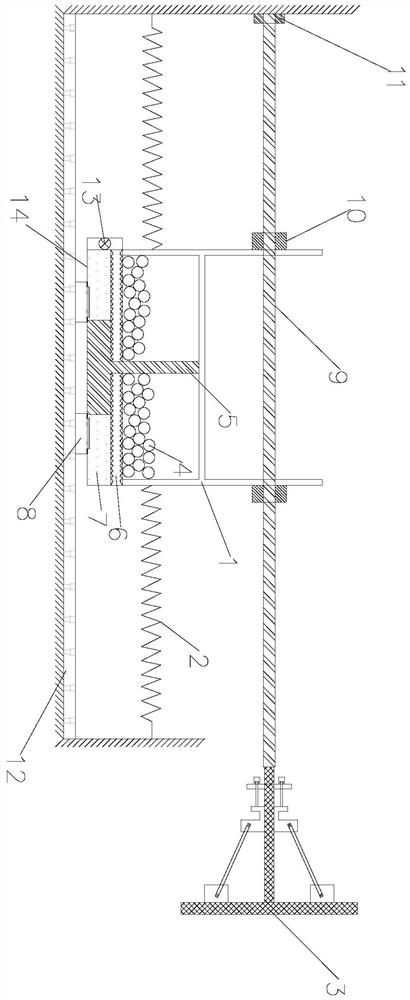
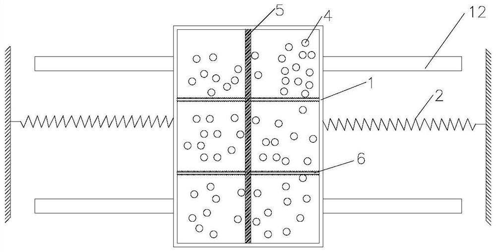
[0032]一种基于亚流态接触应力网络的颗粒惯容系统,其结构如图1和2所示,包括颗粒阻尼单元和可控惯性飞轮,可控惯性飞轮通过螺母10设置于颗粒阻尼单元的上部并让可控惯性飞轮在颗粒阻尼单元往复运动的带动下运行,颗粒阻尼单元两侧通过调谐弹簧2连接。

[0033]具体地,颗粒阻尼单元包括颗粒阻尼器箱体1,颗粒阻尼器箱体1内装填颗粒球2,颗粒阻尼器箱体1底部连接滑块支座8,待减震结构的顶部设置轨道12,滑块支座8滑动设置在轨道12上,使得颗粒阻尼器箱体1能够沿轨道12往复运动。

[0034]具体地,质量块5内置于颗粒阻尼器箱体1中,将颗粒阻尼器箱体1分隔成多个独立腔室;在风 / 地震作用时,质量块5会在颗粒阻尼器箱体1内快速进行往复运动,从而加剧颗粒球4之间的碰撞。

[0035]具体地,质量块5两侧连接有耗能伸缩筒6和储气管道14;两侧储气管道14内的压强相当于弹簧,起到调谐频率的作用;而耗能伸缩筒6不仅能保证腔体的密闭性,而且可以起到耗散系统能量的作用。

[0036]具体地,耗能伸缩筒6一端与质量块5连接,另一端与颗粒阻尼器箱体1连接,能够随质量块5的往复运动而进行伸缩;储气管道14内含有气体7;气体7为惰性气体氩、氮气、二氧化碳中任一种;压力控制器13通过设定压强限值,控制储气管道14内气体7的进出。

[0037]具体地,颗粒球4的材料为陶瓷、钢材、混凝土、石材中的任意一种,直径为2mm-50mm,颗粒球4的体积占腔室体积的30%-60%。

[0038]具体地,丝杠9一端与支座轴承11连接,另一端与可控惯性飞轮3连接。

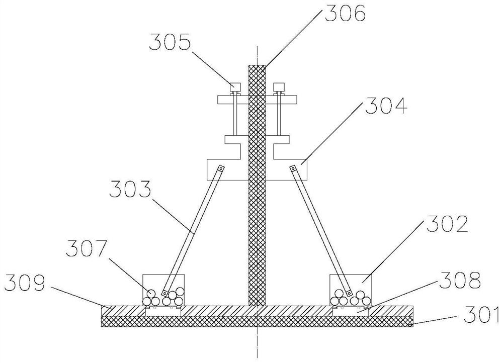
[0039]具体地,可控惯性飞轮3包括飞轮301、箱体302、撑杆303、箍圈304、电机305、主杆306、小颗粒307、滑块308、小滑轨309,其结构如图3和4所示。

[0040]具体地,箱体302内置有小颗粒307;电机305可控制箍圈304沿主杆306上下移动;撑杆303一端与箍圈304连接,另一端与箱体302连接;滑块308上方固定有箱体302,并能够一起沿着小滑轨309进行往复运动。

[0041]具体地,可控惯性飞轮3中的箱体302可沿着小滑轨309进行往复运动,从而不断改变可控惯性飞轮3的惯性矩和惯容系数,由此根据外界激励的频率变化,改变飞轮的惯容系数,实时调整颗粒惯容系统的频率与主结构的第一、二...


PUM

PropertyMeasurementUnit
Diameteraaaaaaaaaa

Abstract

The invention relates to a particle inerter system based on a sub-flow state contact stress network, which comprises a particle damping unit arranged on a track in a sliding manner, and a controllable inertia flywheel arranged at the upper end of the particle damping unit through a lead screw nut assembly, the controllable inertia flywheel is driven by reciprocating motion of the particle damping unit to rotate, and deconstruction, rheology and reconstruction of the particle ball contact stress network can be caused under the action of vibration so as to dissipate energy and attenuate vibration. The controllable inertia flywheel can change the flywheel inerter coefficient according to the frequency change of external excitation, and the frequency of the particle inerter system is adjusted in real time to be consistent with the first-order frequency, the second-order frequency, the third-order frequency and other high-order frequencies of the main structure. The particle inerter system is arranged at the top and in interlayer distribution, and is fixedly mounted at the maximum displacement position of the building structure to be subjected to vibration reduction or a floor with the maximum vibration mode amplitude, and the purposes of multi-stage modal vibration reduction and semi-active control of a main body structure can be achieved.

Description

technical field [0001] The invention belongs to the field of vibration control of civil engineering and mechanical structures, and in particular relates to a particle inertial system based on a subfluid contact stress network. Background technique [0002] The particle damper is a passive control technology evolved from the traditional impact damper. Over the years, it has been deeply researched and applied in the fields of civil engineering, machinery, and aerospace. The particle damper is to fill a certain amount of particles in the limited closed space in the vibrating body or in the additional cavity outside the vibrating body, and use the friction and collision between the particles and between the particles and the wall of the cavity to consume the system. vibration energy, thus providing damping for the main structure and weakening the response of the main structure. Particle damping technology has the advantages of good durability, high reliability, insensitivity to...

Claims


Application Information

Patent Timeline
IPC IPC(8): F16F7/104F16F7/116
CPCF16F7/104F16F7/116
Inventor 鲁正周超杰张家伟
Owner TONGJI UNIV
Learn More