Coupling type radio frequency connector

A radio frequency connector and coupling technology, which is applied in the direction of connection, coupling device, two-part connection device, etc., can solve the problems that the effective and reliable transmission of radio frequency signals cannot be realized, and achieve the effect of effective and reliable transmission and convenient installation and use

Pending Publication Date: 2022-06-24
10TH RES INST OF CETC
View PDF0 Cites 0 Cited by
  • Summary
  • Abstract
  • Description
  • Claims
  • Application Information

AI Technical Summary

Problems solved by technology

[0006] In order to overcome the deficiencies of the prior art, the present invention provides a coupled radio frequency connector, which

Method used


Image

  • Coupling type radio frequency connector
  • Coupling type radio frequency connector
  • Coupling type radio frequency connector

Examples


Example Embodiment

[0029] Example 1

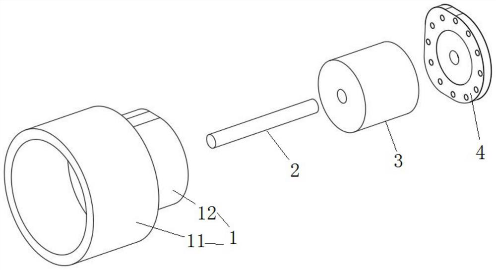
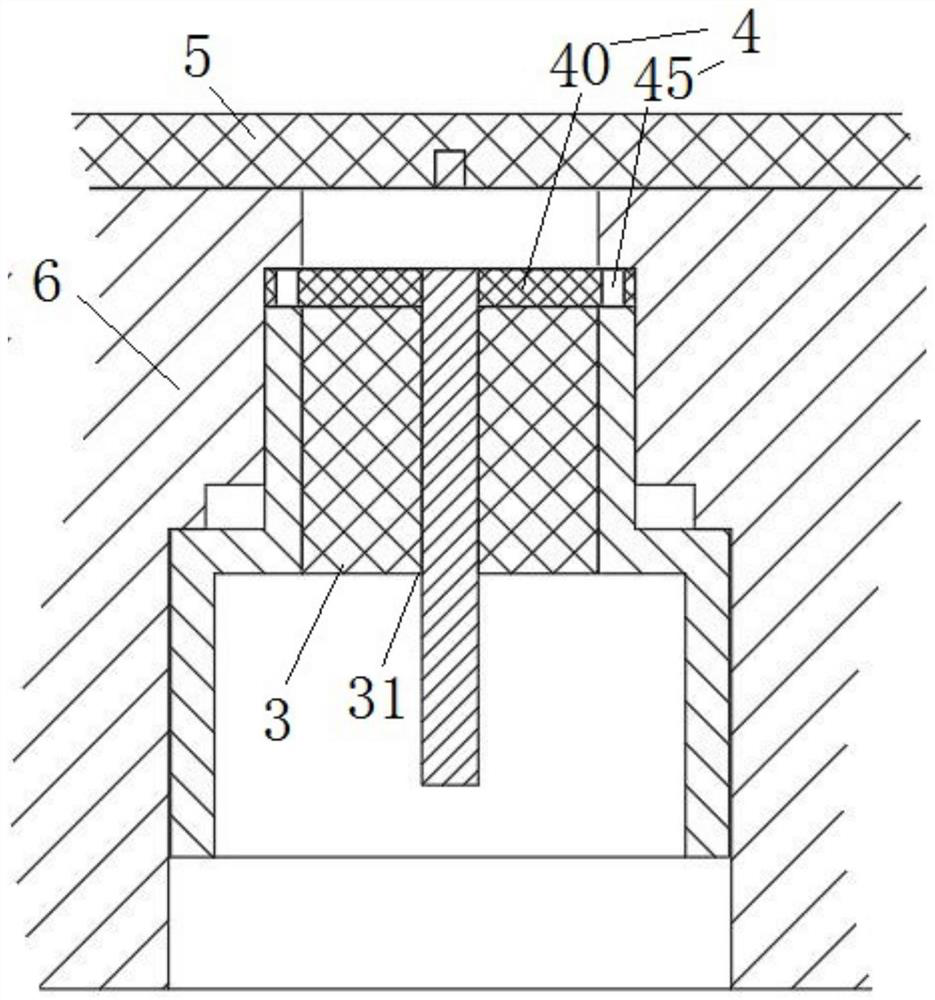
[0030] like Figure 1 to Figure 6 As shown, a coupling type radio frequency connector includes a coaxial shell 1, an inner conductor 2, a medium 3, and a coupling radio frequency board 4 connected in sequence. The coaxial shell 1 is provided with a shell through hole 13, and the medium 3 There is a medium through hole 31 on it, one end of the inner conductor 2 is inserted into the outer casing through hole 13, the other end of the inner conductor 2 is inserted into the medium through hole 31, and the coaxial outer casing 1 and the Coupling with RF board 4.

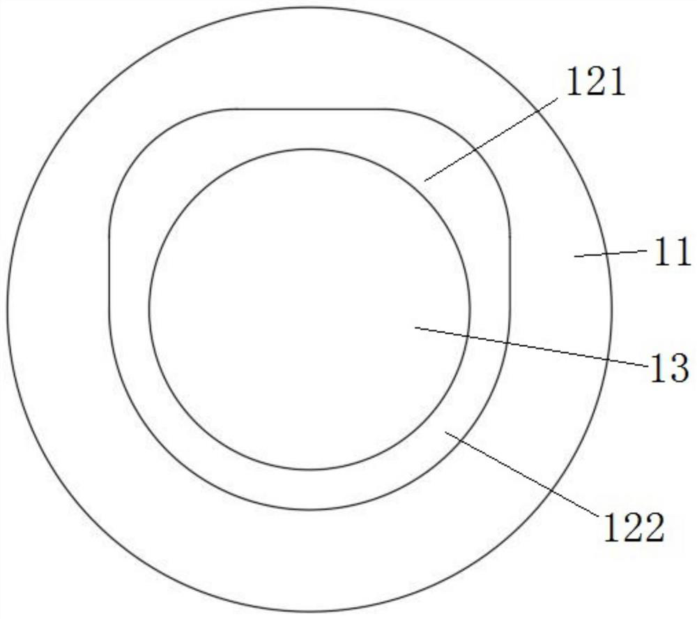
[0031] As a preferred technical solution, the coaxial housing 1 includes a top portion 11 and a tail portion 12 that are connected to each other, and the housing through hole 13 is provided on the tail portion 12 .

[0032] As a preferred technical solution, the tail portion 12 includes a rectangular body 121 and a semicircular body 122 spliced ​​to each other. The surface of the rectangular body 121 p...

Example Embodiment

[0040] Example 2

[0041] like Figure 1 to Figure 6 As shown, as a further optimization of Embodiment 1, this embodiment includes all the technical features of Embodiment 1. In addition, this embodiment also includes the following technical features:

[0042] The present invention aims to provide a radio frequency connector with high stability and reliability, and at the same time, the inner conductor will not be higher than the surface of the printed board.

[0043] A coupled radio frequency connector for transmitting radio frequency signals, the coupled radio frequency connector includes a coaxial shell 1, an inner conductor 2, a medium 3 and a coupled radio frequency board 4.

[0044] The shape of the top of the coaxial housing 1 is a cylinder, and the shape of the tail is an arc arch. The medium 3 is installed in the circular hole at the end of the coaxial casing 1, and the inner conductor 2 is installed in the circular hole of the medium 3. The coupling RF board 4 is ...


PUM


Abstract

The invention relates to the technical field of radio frequency connectors, and discloses a coupling type radio frequency connector which comprises a coaxial shell, an inner conductor, a medium and a coupling radio frequency board which are sequentially connected, a shell through hole is formed in the coaxial shell, a medium through hole is formed in the medium, one end of the inner conductor is inserted into the shell through hole, and the other end of the inner conductor is inserted into the coupling radio frequency board. And the other end of the inner conductor is inserted into the medium through hole. The problem that in the prior art, effective and reliable transmission of radio frequency signals cannot be achieved is solved.

Description

technical field [0001] The invention relates to the technical field of radio frequency connectors, in particular to a coupled radio frequency connector. Background technique [0002] RF signal transmission between independent modules usually requires RF connectors to achieve low-loss signal transmission while ensuring that the modules are easy to disassemble. For high-density vertical interconnect application scenarios, the bottom of the connector is usually fed. The bottom feeding of the connector means that the feeding coaxial probe is perpendicular to the printed board. By adjusting the impedance value of the feeding coaxial end and the printed board end transmission line or antenna unit, the impedance matching can be achieved, and the reflection coefficient can be reduced, so as to achieve the electromagnetic signal. The purpose of good transmission. [0003] The bottom feed form of the traditional RF connector to the RF printed board is mainly: the inner conductor pin...

Claims


Application Information

Patent Timeline
IPC IPC(8): H01R24/50
CPCH01R24/50
Inventor 何林涛朱朕宾孙凤林蓝海
Owner 10TH RES INST OF CETC
Why Eureka
Try Eureka