
Low-torque valve element sleeve

A spool sleeve and low torque technology, which is applied in the field of spool sleeves and low torque spool sleeves, can solve problems such as not being able to meet low torque

Pending Publication Date: 2022-07-01
ZHENJIANG HYDRAULICS
View PDF1 Cites 0 Cited by
  • Summary
  • Abstract
  • Description
  • Claims
  • Application Information

AI Technical Summary

Problems solved by technology

Practice shows that the traditional spool sleeve can no longer meet the requirements of low torque and needs to be improved

Method used


Image

  • Low-torque valve element sleeve
  • Low-torque valve element sleeve
  • Low-torque valve element sleeve

Examples


Embodiment 1

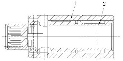
[0024] The low-torque valve core sleeve of this embodiment is a preferred embodiment. For the basic structure, please refer to figure 1 , which is composed of a valve core 2 with a transmission input at one end and a transmission output at the other end and a valve sleeve 1 sleeved outside it.

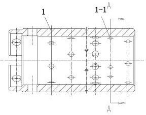
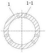
[0025] The specific structure of the valve sleeve 1 is as follows: Image 6 , Figure 7 As shown, there are seven groups of flow channel switching holes distributed at axial intervals, and the second row of flow channel switching holes adjacent to the transmission output end contains three pairs of circumferentially evenly distributed switching perforations 1-1 with a pair of two adjacent holes. The hydraulic pressure of the valve core sleeve is subject to hydraulic fluctuations, so the outer sides of the two adjacent holes are respectively added with transition holes 1-2.

[0026] The specific structure of valve core 2 is as follows Figure 8 , Figure 9 As shown, the outer circl...


PUM


Abstract

The invention relates to a low-torque valve element sleeve, and belongs to the technical field of hydraulic transmission parts. The product is formed by combining a valve core and a valve sleeve, the valve sleeve is provided with a plurality of groups of runner switching holes which are axially distributed at intervals, each group of runner switching holes comprises a plurality of switching through holes which are circumferentially distributed, and transition through holes are formed beside the switching through holes of at least one group of runner switching holes; a flow channel switching groove is formed in the outer circle of the valve element, a set of axially-extending switching grooves distributed in the circumferential direction are formed in the position, corresponding to the axial position of the switching penetrating hole, of the valve element, one ends of the switching grooves are communicated through circumferential annular grooves, and transition blind holes are formed in the positions, corresponding to the axial position of the transition penetrating hole, between the adjacent switching grooves. A pressure equalizing structure which plays a role all the time is formed, so that the pressure of the whole valve element sleeve is equal everywhere, the situation that the steering torque is increased due to deformation of the valve element sleeve caused by uneven distribution of hydraulic pressure is effectively avoided, and the requirement for acceleration development of engineering vehicles is met.

Description

technical field [0001] The invention relates to a valve core sleeve, in particular to a low-torque valve core sleeve, and belongs to the technical field of hydraulic transmission parts. Background technique [0002] The valve core sleeve is composed of the valve core and the valve sleeve sleeved outside it. It is the core component of the full hydraulic steering gear (for its typical structure, see the Chinese patent document with the application number of 201110195256.9 and the name "Full Hydraulic Steering Gear"). Its function is to switch the oil circuit on demand to achieve the required steering control. For a long time, the traditional valve core sleeve structure such as Figure 1 to Figure 5 As shown in the figure, it is composed of a valve core 2 with a transmission input at one end and a transmission output at the other end, and a valve sleeve 1 sleeved outside it. The second row of flow channel switching holes at the output end contains three pairs of circumferenti...

Claims


Application Information

Patent Timeline
IPC IPC(8): F16K5/04F16K5/08F16K27/06F16K5/12F15B13/02B62D5/08
CPCF16K5/0407F16K5/08F16K27/065F16K5/12F15B13/02B62D5/08
Inventor 焦文瑞秦志文张兆利侯巍潘骏
Owner ZHENJIANG HYDRAULICS
Learn More