

Long tunnel structure pseudo-static anti-seismic test device and test method
A technology for long tunnels and seismic testing, applied in the testing of machine/structural components, measuring devices, vibration testing, etc., can solve the problem of inability to simulate the seismic response of the structure, overcome the problem of table size limitations, facilitate operation, reduce The effect of size effect
Pending Publication Date: 2022-07-05
HOHAI UNIV
View PDF11 Cites 4 Cited by
- Summary
- Abstract
- Description
- Claims
- Application Information
AI Technical Summary
Problems solved by technology
[0004] To sum up, at present, the shaking table test of long tunnel structures is limited by equipment, and smaller scale models are often used, which cannot simulate the real seismic response of the structure. A simple, practical and large-scale lon
Method used
View moreImage
Smart ImageViewing Examples

Examples
 PUM
 Abstract
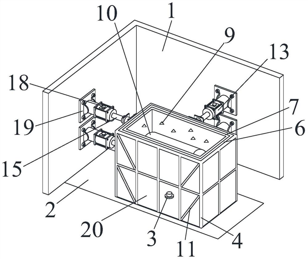
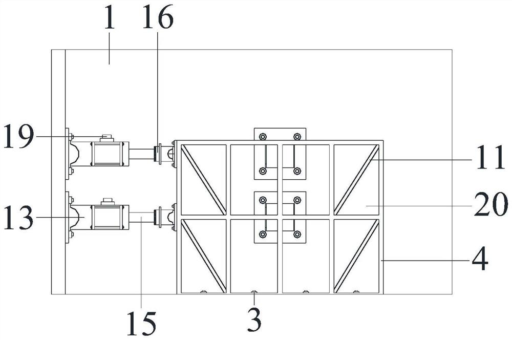
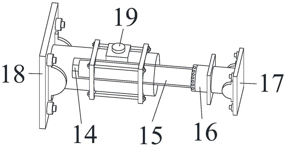
The invention relates to a pseudo-static anti-seismic test device and method for a long tunnel structure. The pseudo-static anti-seismic test device comprises a counter-force structure, a loading structure and a cubic rigid model box, the counter-force structure comprises a counter-force pedestal and a counter-force wall, and the counter-force wall is of an L-shaped structure and is annularly arranged around the counter-force pedestal; a cubic rigid model box is placed on the surface of the counter-force pedestal, and a surrounding rock similar material for test simulation and a long tunnel structure model are placed in the cubic rigid model box; the loading structure comprises four hydraulic actuators which are vertically arranged, the upper actuator is connected with the second layer of the model box, the lower actuator is connected with the first layer of the model box, and the inertia force distribution mode of the structure is simulated through different applied forces during loading; according to the invention, the size effect influence caused by a vibration table reduced scale model can be reduced, large-scale tunnel structure model test analysis is realized, the earthquake action is simulated through force-displacement hybrid control, and the earthquake dynamic response of a long and large tunnel is better simulated.
Description
technical field [0001] The invention relates to a pseudo-static anti-seismic test device and a test method for a long tunnel structure, and belongs to the field of underground structure anti-seismic pseudo-static test equipment. Background technique [0002] At present, seismic simulation shaking table test is a common method to study the seismic dynamic response of tunnel structures. However, due to the limitation of the bearing capacity of the shaking table and the size of the table, most of them can only carry out small scale model tests, especially for long tunnels, the over-simplified test structure model seriously affects the authenticity of the shaking table test results. If the scale of the test model can be increased, that is, to realize the tunnel structure test of a larger model, the size effect can be reduced. On the other hand, the larger test model box can also simulate the influence of different geological conditions and structures across faults. [0003] At ...
Claims
Login to View More Application Information
Patent Timeline
 IPC IPC(8): G01M7/02
CPCG01M7/02
Inventor戴伦朱珍德张聪朱端王麓翔朱姝周露明吕茂淋
OwnerHOHAI UNIV