Medical bag waterproof detection equipment based on intelligent bag
A technology for testing equipment and bags, applied in the direction of detecting the appearance of fluid at the leak point, using liquid/vacuum for liquid tightness measurement, etc. and other problems to achieve the effect of improving the accuracy
- Summary
- Abstract
- Description
- Claims
- Application Information
AI Technical Summary
Problems solved by technology
Method used
Image

Examples
Embodiment 1
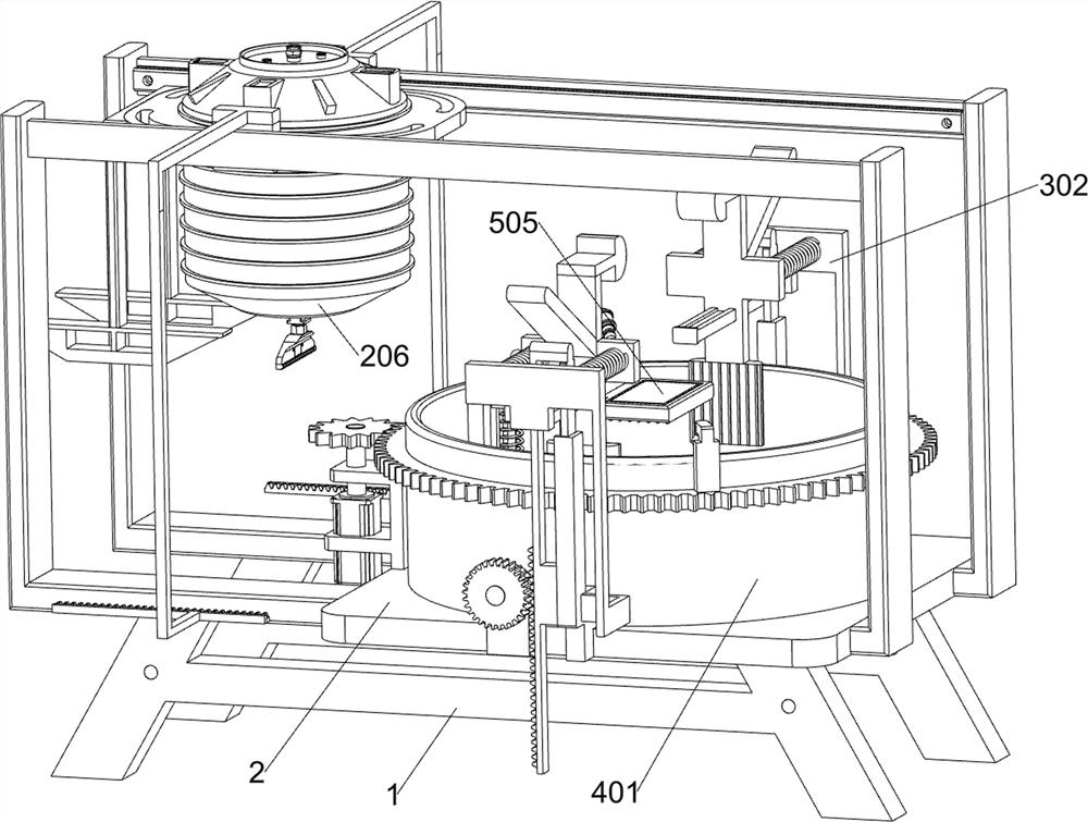
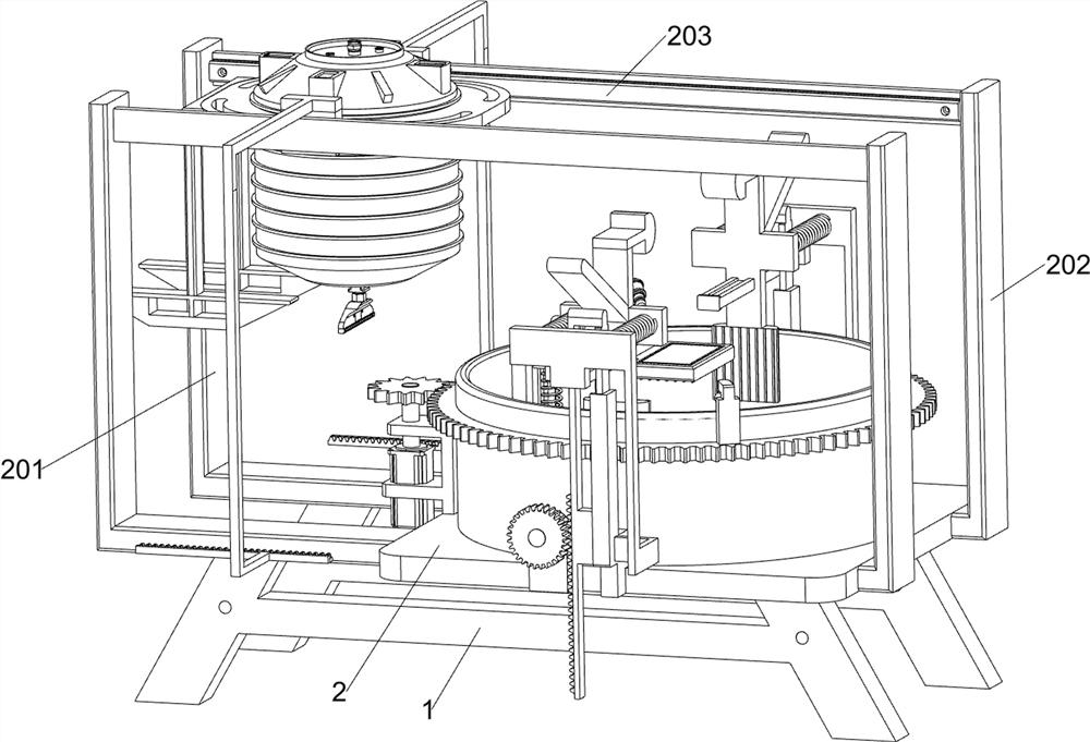
[0033] A medical bag waterproof detection equipment based on smart luggage, according to Figure 1-3 As shown, it includes a bracket 1, a bearing plate 2, a water injection unit, a limit unit and a detection unit; the bracket 1 is provided with two; the bearing plate 2 is fixedly connected between the two brackets 1; the bearing plate 2 is connected with a water injection unit; The middle part of the load-bearing plate 2 is connected with a limiting unit; the middle part of the upper surface of the load-bearing plate 2 is connected with a detection unit.
[0034] When working, the staff will move the load-bearing plate 2 to the designated position and keep the two brackets 1 horizontal, and then the staff will place the waterproof medical bag in the detection unit, and then the water injection unit will move to the detection unit. , At this time, the water injection unit operates to drive the limit unit to operate, the limit unit operates to limit the waterproof medical bag, a...
Embodiment 2
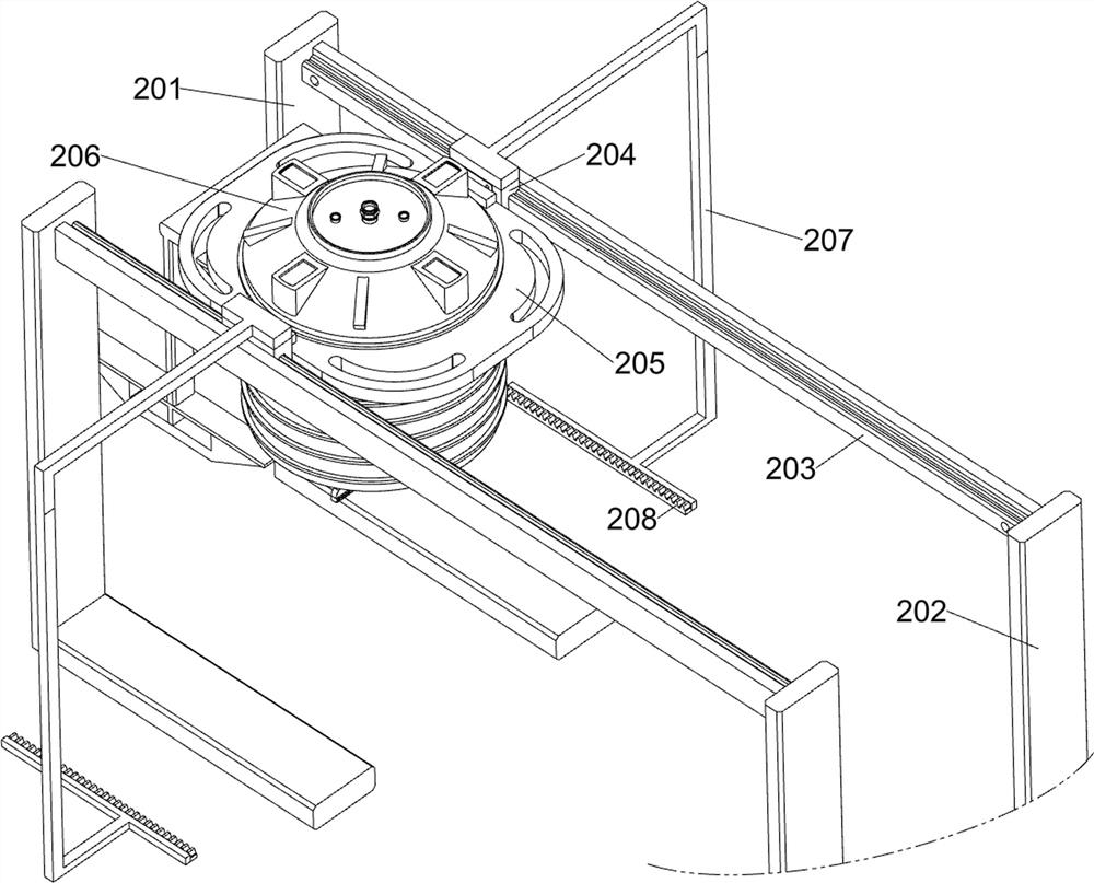
[0036] On the basis of Example 1, according to figure 1 and Figure 4-11As shown, the water injection unit includes a first fixing frame 201 , a first supporting frame 202 , an electric sliding rail 203 , an electric sliding block 204 , a first fixing plate 205 , a water bucket 206 , a connecting frame 207 , a first rack 208 and a spray head 209 ; The left side of the bearing plate 2 is fixed with two first fixing frames 201; the right side of the bearing plate 2 is fixed with two first supporting frames 202; An electric sliding rail 203 is connected; an electric sliding block 204 is slidably connected to the two electric sliding rails 203; a first fixing plate 205 is fixedly connected between the two electric sliding blocks 204; A water bucket 206; a connecting frame 207 is fixedly connected to the upper part of the two electric sliders 204; a first rack 208 is fixedly connected to the lower part of the two connecting frames 207;
[0037] The limiting unit includes a second...
Embodiment 3
[0044] On the basis of Example 2, according to figure 1 and Figure 12-13 As shown, it also includes a re-inspection unit; the left part of the water injection unit is connected with a re-inspection unit; the re-inspection unit is connected with the detection unit; plate 504, pressure plate 505, spring rod 506, second fixing rod 507 and connecting rod 508; the left part of the first fixing plate 205 is fixed with a mounting frame 501; the lower part of the mounting frame 501 is fixed with two third fixing plates 502 The lower part of the two third fixing plates 502 is fixed with a pressing plate 503; the bottom of the inner wall of the detection barrel 401 is fixed with a fourth fixing plate 504; the upper part of the fourth fixing plate 504 is slidably connected with a pressing plate 505; The lower surface of the 505 is fixed with a spring rod 506; the spring rod 506 is fixed with the fourth fixing plate 504; the middle of the pressure plate 505 is fixed with a connecting ro...
PUM
 Abstract
Description
Claims
Application Information
 - R&D
- Intellectual Property
- Life Sciences
- Materials
- Tech Scout
- Unparalleled Data Quality
- Higher Quality Content
- 60% Fewer Hallucinations
Browse by: Latest US Patents, China's latest patents, Technical Efficacy Thesaurus, Application Domain, Technology Topic, Popular Technical Reports.
© 2025 PatSnap. All rights reserved.Legal|Privacy policy|Modern Slavery Act Transparency Statement|Sitemap|About US| Contact US: help@patsnap.com