Supercharge Your Innovation With Domain-Expert AI Agents!

A motor waterproof test device

A test device and test box technology, which is applied in the application of electrical devices to test fluid tightness, etc., can solve the problems of affecting the use of motors, low test efficiency, and fixed and single installation environment, so as to achieve convenient operation, improve use performance and scope of application, The effect of simple structure

Active Publication Date: 2021-04-09
无锡中吉泰电气科技有限公司
View PDF9 Cites 0 Cited by
  • Summary
  • Abstract
  • Description
  • Claims
  • Application Information

AI Technical Summary

Problems solved by technology

[0004] The purpose of the present invention is to solve the existing problem in the prior art that the installation environment of the test device for the motor is relatively fixed and single, not only the test efficiency is low, but also the environmental conditions of the test cannot be flexibly changed according to different test requirements, and it cannot be tested from various aspects. Test the waterproofness of the motor, which affects the shortcomings of the later use of the motor, and proposes a motor waterproof test device

Method used


Image

  • A motor waterproof test device
  • A motor waterproof test device
  • A motor waterproof test device

Examples


Embodiment 1

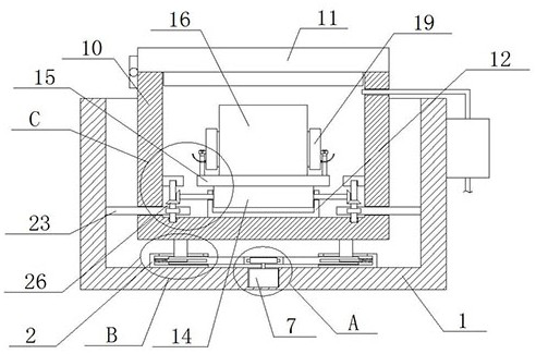
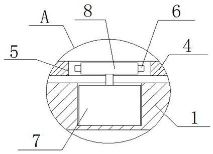
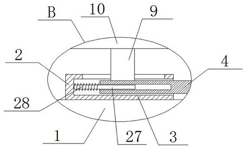
[0022] refer to Figure 1-5 , a motor waterproof testing device, comprising a fixed seat 1, the top of the fixed seat 1 is provided with a test slot, the bottom of the test slot is fixedly installed with two mounting plates 2, and the sides of the two mounting plates 2 are provided with mounting plates. Slot 3, the same connecting plate 4 is slidingly installed in the two mounting grooves 3, and the connecting plate 4 is provided with a driving device. The top of the connecting plate 4 is fixedly installed with two moving columns 9, and the tops of the two moving columns 9 are fixed There is the same test box 10, the top of the test box 10 is an opening, the opening of the test box 10 is equipped with a case cover 11, the bottom inner wall of the test box 10 is fixedly equipped with a mounting seat 12, and the top of the mounting seat 12 is provided with a fixed Groove 13, rotating seat 14 is installed in fixed groove 13, is provided with control device on both sides inner wal...

Embodiment 2

[0030] refer to Figure 1-5 , further improvements have been made on the basis of Example 1:

[0031] A motor waterproof testing device, comprising a fixed seat 1, a test slot is provided on the top of the fixed seat 1, and two mounting plates 2 are fixed on the bottom of the test slot by bolts, and two mounting plates 2 are provided on the sides close to each other. Mounting groove 3, the same connecting plate 4 is slidingly installed in the two mounting grooves 3, and the connecting plate 4 is provided with a driving device. The same test case 10 is fixedly installed on the top by bolts, the top of the test case 10 is an opening, and the opening of the test case 10 is rotated with a case cover 11, and the bottom inner wall of the test case 10 is fixed with a mounting seat 12 by bolts. The top of the seat 12 is provided with a fixed groove 13, and a rotating seat 14 is installed in the fixed groove 13, and a control device is arranged on the inner wall of both sides of the t...


PUM


Abstract

The invention belongs to the field of electric motors, in particular to a waterproof test device for electric motors. The installation environment of the electric motor is relatively fixed and single for the existing test devices. Not only is the test efficiency low, but it is also impossible to flexibly change the test method according to different test requirements. Due to environmental conditions, the waterproofness of the motor cannot be tested from many aspects, which will affect the later use of the motor. The following plan is proposed, which includes a fixing seat. A test slot is opened on the top of the fixing seat, and two As for the mounting plate, mounting grooves are provided on the sides of the two mounting plates close to each other, the same connecting plate is slidably installed in the two mounting grooves, and a driving device is arranged on the connecting plate. The invention has simple structure and convenient operation. The test device can flexibly change the test environment conditions of the motor according to different test requirements, thereby greatly improving its own performance and application range, and can test the waterproofness of the motor from various aspects.

Description

technical field [0001] The invention relates to the technical field of motors, in particular to a motor waterproof testing device. Background technique [0002] In various places such as agricultural irrigation, urban water supply, building drainage, etc., a large number of motors are often used, so the requirements for the waterproof performance of the motors are greatly increased at this time. Correspondingly, waterproof performance tests are also required for the produced motors. , to ensure the subsequent normal use of the motor. However, for existing test devices, it is often only to statically soak the motor in test water, and after soaking for a certain period of time, the motor is taken out and the insulation resistance is measured; [0003] However, the existing testing devices have a relatively fixed environment for the installation of the motor, which not only has low test efficiency, but also cannot flexibly change the test environmental conditions according to ...

Claims


Application Information

Patent Timeline
Patent Type & Authority Patents(China)
IPC IPC(8): G01M3/40
CPCG01M3/40
Inventor 查洪雁
Owner 无锡中吉泰电气科技有限公司
Features
  • R&D
  • Intellectual Property
  • Life Sciences
  • Materials
  • Tech Scout
  • Unparalleled Data Quality
  • Higher Quality Content
  • 60% Fewer Hallucinations
Learn More