Liquid filter and volume compensation element for liquid filter

A technology of liquid filter and volume compensation, which is applied in the direction of membrane filter, fixed filter element filter, filtration separation, etc., and can solve the problem of damage to the liquid filter shell and so on

Pending Publication Date: 2022-07-12
ROBERT BOSCH GMBH
View PDF1 Cites 0 Cited by
  • Summary
  • Abstract
  • Description
  • Claims
  • Application Information

AI Technical Summary

Problems solved by technology

There is thereby a possible risk of damage to the housing of the liquid filter due to the increase in volume

Method used


Image

  • Liquid filter and volume compensation element for liquid filter
  • Liquid filter and volume compensation element for liquid filter
  • Liquid filter and volume compensation element for liquid filter

Examples


Embodiment Construction

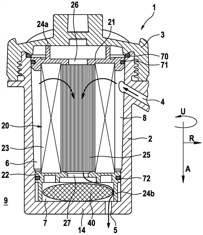
[0081] Figure 1 shows a schematic cross-section of a liquid filter 1 of the prior art.

[0082] The liquid filter 1 includes a housing 2 having a cover 3 , a liquid inflow port 4 , a liquid outflow port 5 , and a filter element 20 . The filter element 20 is arranged in the interior 6 of the housing 2 and has a first end cap 21 , a second end cap 22 facing the cover 3 and a filter medium 23 arranged in the axial direction A between the two end caps 21 , 22 . The second end cap 22 here faces towards the bottom 14 of the housing 2 , which is constructed here in the form of a cup. The direction of gravity can be directed from the cover 3 to the base 14 , for example. The filter element 20 separates the clean side 7 (on which the filtered liquid is present) from the raw side 8 (on which the liquid to be filtered lies). The first end cap 21 has a channel-shaped first opening 26 . The second end cap 22 has a channel-shaped second opening 27 . The filter insert 20 is here formed ...


PUM


Abstract

The invention relates to a liquid filter. The invention relates to a liquid filter having: a housing (2) comprising a cover (3); and a liquid inlet (4) and a liquid outlet (5); and a filter insert (20) which is arranged in the interior (6) of the housing (2) and has a first end shield (21) facing the cover (3), a second end shield (22) and a filter medium (23) which is arranged in the axial direction (A) between the two end shields (21, 22), the filter insert (20) separating the clean side (7) from the original side (8). Furthermore, the liquid filter has a volume compensation element (40) comprising an elastically reversibly compressible central body (41) having a central body interior (42), the central body interior (42) enclosing the initial volume in an uncompressed state and enclosing the final volume in a compressed state, the volume difference between the final volume and the initial volume corresponds to at least 35% of the maximum volume change of the liquid in the liquid filter (1) at normal pressure in a temperature range between + 90 DEG C and-40 DEG C. Here, the volume compensation element (40) has a first sealing region (50) surrounding the central body (41), the first sealing region (50) being designed to interact with the housing (2) and the cover part (2) in the fully assembled state of the liquid filter (1) such that the interior (6) of the housing is sealed in a fluid-tight manner from the exterior space (9) of the liquid filter (1). Here, the volume compensation element (40) has a second sealing region (60) surrounding the central body (41), the second sealing region (60) being designed to prevent a fluid short circuit between the clean side (7) and the original side (8).

Description

technical field [0001] The present invention relates to a liquid filter and a volume compensation element for the liquid filter. Background technique [0002] In a liquid filter, depending on the type of liquid to be filtered, it can happen that the liquid in the liquid filter strongly changes its specific volume and / or takes up another state of matter with a temperature change and thus produces a strong volume increase. Large (such as when water freezes into ice). There is thus a risk that the housing of the liquid filter will be damaged by the increase in volume. [0003] Therefore, it is known from the prior art that in liquid filters, which are used, for example, in liquid urea solutions (DENOX) for catalytic reduction of nitrogen oxides in the automotive field, a volume compensation element is provided in the interior of the housing, The volume compensation element is not filled with liquid, but is elastically deformable. When the volume of the liquid in the housing ...

Claims


Application Information

Patent Timeline
Patent Type & Authority Applications(China)
IPC IPC(8): B01D29/21
CPCB01D29/21B01D2201/295B01D2201/347B01D2201/342B01D2201/0415
Inventor J·L·阿里亚斯阿里亚斯
Owner ROBERT BOSCH GMBH
Why Eureka
Try Eureka