Portable medical image film reader

A portable and film-reading technology, applied in the direction of instruments, optical components, optics, etc., to achieve the effect of avoiding infection and ensuring distance

Inactive Publication Date: 2022-07-15
朱明亮
View PDF1 Cites 0 Cited by
  • Summary
  • Abstract
  • Description
  • Claims
  • Application Information

AI Technical Summary

Problems solved by technology

[0004] The purpose of the present invention is to provide a portable medical image reader to solve the problems in the above-mentioned background

Method used


Image

  • Portable medical image film reader
  • Portable medical image film reader
  • Portable medical image film reader

Examples


Embodiment Construction

[0031] The technical solutions in the embodiments of the present invention will be clearly and completely described below with reference to the accompanying drawings in the embodiments of the present invention. Obviously, the described embodiments are only a part of the embodiments of the present invention, but not all of the embodiments. Based on the embodiments of the present invention, all other embodiments obtained by those of ordinary skill in the art without creative efforts shall fall within the protection scope of the present invention.

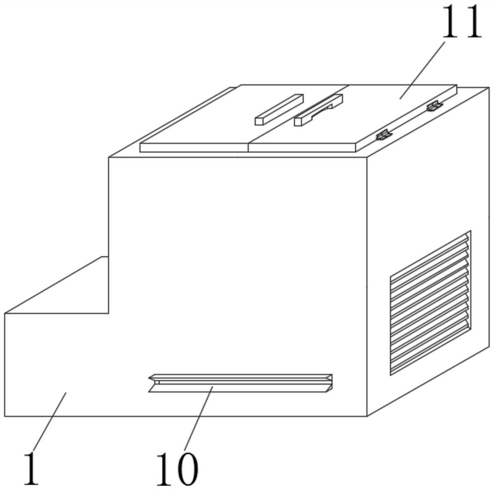
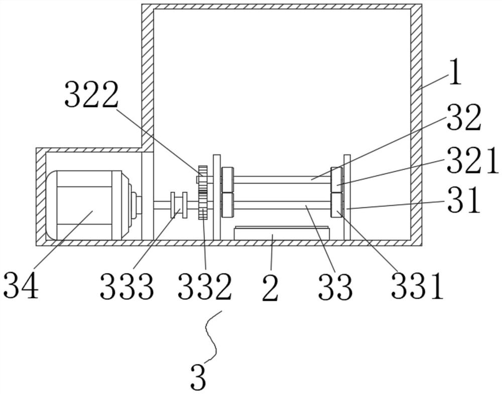
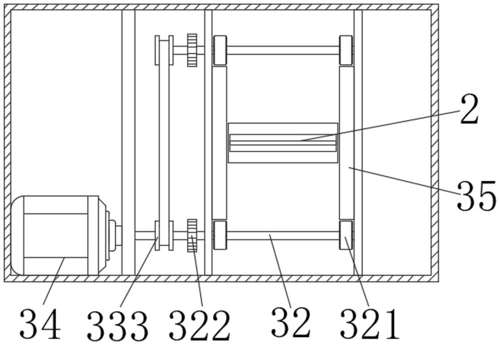
[0032] see figure 1 - Figure 9 As shown, the present invention is a portable medical image reader, including a case 1, and a film inlet 10 and a film outlet 100 are respectively opened on two opposite sides of the case 1. When using, just insert the film through the film inlet 10. , the film is output through the film outlet 100 after being read by the film reader;

[0033] Specifically, refer to figure 2 , image 3 , Figure 5...


PUM


Abstract

The invention discloses a portable medical image film reader which comprises a case, a film inlet and a film outlet are respectively formed in two opposite side surfaces of the case, and films are output through the film outlet after being read by the film reader as long as the films are inserted from the film inlet; after the film reader reads and recognizes the film, information on the film can be recognized, displayed and presented on the upper screen and the lower screen, the information on the film can be visually displayed on the upper screen and the lower screen, and the two screens are arranged to be spliced, so that the information display area on the film, such as picture information, is increased; the magnifying lens can be effectively magnified, so that a patient can visually see the magnifying lens conveniently, and the problem of inconvenient communication is solved under the condition that the distance between a doctor and the patient needs to be kept.

Description

technical field [0001] The invention relates to the technical field of medical image reading, in particular to a portable medical image reading device. Background technique [0002] A utility model with publication number CN209198774U, a medical image film reader, comprising a seat, a light box, a water tank and a film adsorption plane arranged on the surface of the light box; the light box is arranged on the seat, the film adsorption plane is vertical or inclined, and the film adsorption plane There are a plurality of diversion grooves extending from top to bottom. The diversion grooves divide the film adsorption plane into several adsorption areas. The upper end of the film adsorption plane is provided with a nozzle opposite to the diversion groove, and the water tank is provided with a nozzle connected to the nozzle. The lower end of the film adsorption plane is provided with a water tank opposite to the diversion groove; the light box is provided with a cavity, the cavit...

Claims


Application Information

Patent Timeline
Patent Type & Authority Applications(China)
IPC IPC(8): G02B27/02
CPCG02B27/026G02B27/028
Inventor 朱明亮张来勇
Owner 朱明亮
Why Eureka
Try Eureka