Automatic hub clamping positioner for robot grinding and polishing

A positioner and robot technology, applied in the direction of grinding drive device, grinding/polishing equipment, grinding machine tool parts, etc., can solve the problems of inability to position and fix the hub, inconvenient operation of the fixing method, and low machining accuracy , to achieve the effect of simple structure, fast and convenient clamping, and improved processing efficiency

Active Publication Date: 2022-07-22
HARBIN INST OF TECH
View PDF15 Cites 0 Cited by
  • Summary
  • Abstract
  • Description
  • Claims
  • Application Information

AI Technical Summary

Benefits of technology

This patented technology describes a system called Automobile Ground Hub (AGH) Clamper Controllers (CSC). These systems help control the movement of wheels on vehicles without affecting their overall design or functionality. They allow robotic arms to hold these components securely while they perform various tasks like milling or polishings. Additionally, there has been developed another automated CSHLCluster System (ACS), where ACS machines replace human workers' labor force more efficiently than traditional methods such as sand blast clean-outs. Overall, this technical solution allows for efficient manufacturing processes involving complicated surfaces and shapes of vehicle parts.

Problems solved by technology

The technical problem addressed in this patented text relates to improving the precision and ease-of-use (LC) performance when applying industrial robotic arms to workpiece processing applications such as turning or milling processes due to variations between specifications caused by manufacturing tolerances that may affect their placement within certain dimensions. This issue becomes even more challenges because these machines have unique features like asymmetry about which parts they belong to: shafts made from metal tubular material called steel pipes, drums containing rubber cushionings inside them, and discs attached to both ends of each drum. These components make precise alignment difficult without causing damage if applied directly onto the surface being worked upon. Additionally, there exist issues related to how well the machine works properly at various stages of its lifecycle - whether it needs to perform multiple steps before starting production again after use or just start working once started.

Method used


Image

  • Automatic hub clamping positioner for robot grinding and polishing
  • Automatic hub clamping positioner for robot grinding and polishing
  • Automatic hub clamping positioner for robot grinding and polishing

Examples


specific Embodiment approach 1

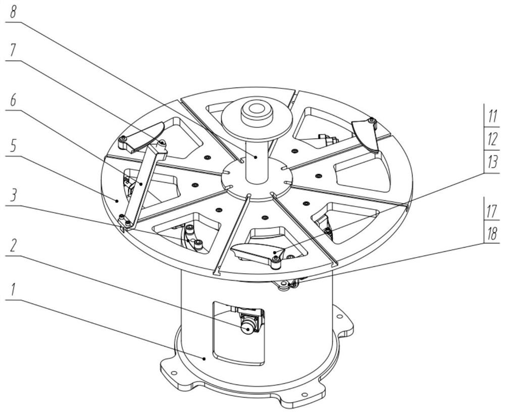
[0025] Specific implementation mode 1: refer to Figure 1 to Figure 5 This embodiment will be described. This embodiment provides an automatic wheel hub clamping and positioning machine for robot grinding and polishing. The automatic clamping and positioning machine includes a base 1, a driving mechanism, a turntable 5, an auxiliary fixing mechanism, and a central positioning shaft. 8 components and N clamping and fixing components, N is a positive integer greater than 3;

[0026] The drive mechanism is installed in the base 1, and the power output end of the drive mechanism passes through the top surface of the base 1 and is arranged outside the base 1, the turntable 5 is arranged above the base 1, and the turntable 5 is connected to the drive. The power output end of the mechanism is detachably connected, the auxiliary fixing mechanism is arranged at the edge of the upper surface of the turntable 5, and the auxiliary fixing mechanism is detachably connected with the turntabl...

specific Embodiment approach 2

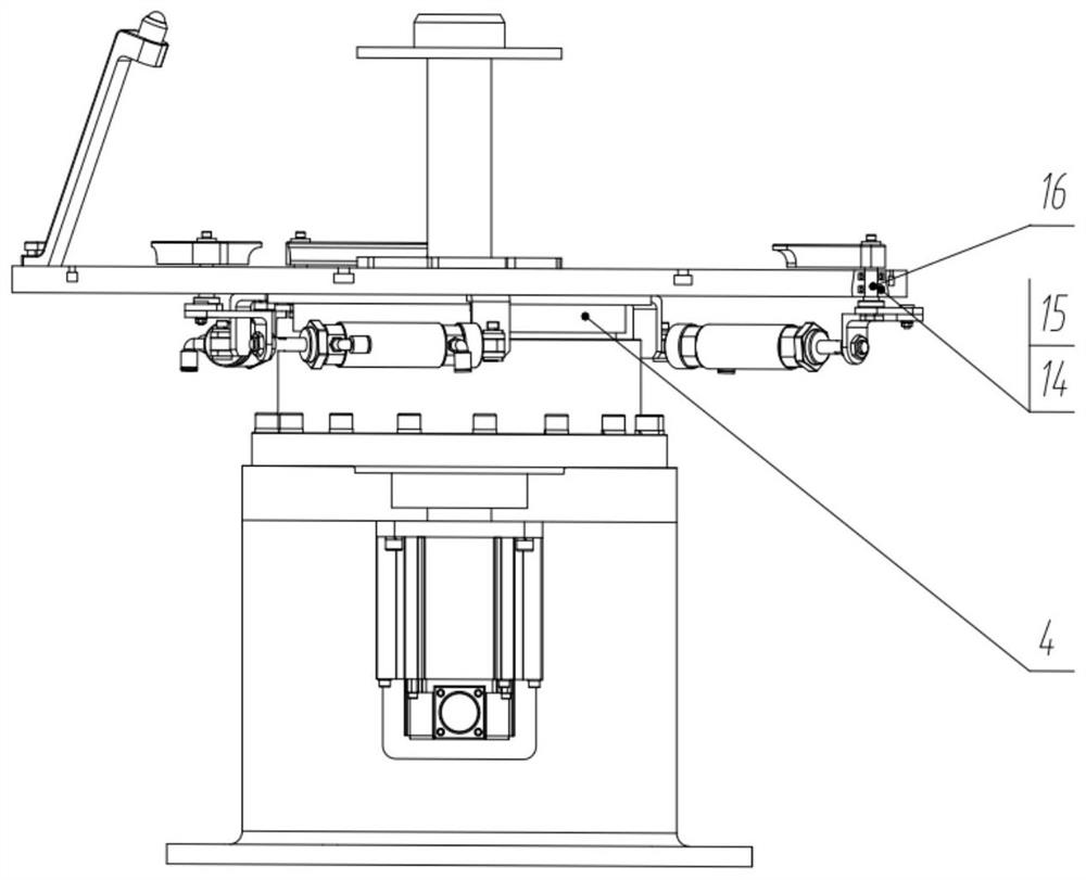
[0028] Specific implementation two: refer to Figure 1 to Figure 5 This embodiment is described. This embodiment further defines the driving mechanism described in the specific embodiment 1. In this embodiment, the driving mechanism includes a motor 2, a reducer 3 and a Farah disc 4. The motor 2 is fixed by a motor mounting bracket. Installed in the base 1, and the output shaft of the motor 2 is arranged vertically upward, the reducer 3 is arranged on the output shaft of the motor 2, and the power input shaft of the reducer 3 is connected with the output shaft of the motor 2 through a coupling, The power output shaft of the reducer 3 is arranged vertically upward, the shell of the reducer 3 is disassembled and connected to the upper surface of the base 1 through bolts, the Fara disc 4 is sleeved on the power output shaft of the reducer 3, and the axis of the Fara disc 4 is connected to the upper surface of the base 1. The axes of the power output shafts in the reducer 3 are ar...

specific Embodiment approach 3

[0030] Specific implementation mode three: refer to Figure 1 to Figure 5This embodiment is described. This embodiment further defines the turntable 5 described in the second embodiment. In this embodiment, a center hole is machined in the center of the upper surface of the turntable 5, and the center positioning shaft assembly 8 is correspondingly inserted in the In the center hole on the turntable 5, the upper surface of the turntable 5 is machined with a plurality of guide chutes equidistantly along the circumferential direction. At the edge of 5, a weight-reducing through hole is machined on the fan-shaped table body between two adjacent guide chutes. Other compositions and connection methods are the same as those in the second embodiment.

[0031] In this embodiment, the center hole in the turntable 5 is used for cooperating with the center positioning shaft assembly 8, and the guide chute is a T-shaped groove, which is used to provide a guide and sliding space for the a...


PUM


Abstract

The invention discloses an automatic hub clamping positioner for robot grinding and polishing, belongs to the technical field of hub machining, and aims to solve the problems that the machining precision is low due to the fact that an existing hub machining platform cannot position and fix a hub, and an existing positioner for automobile hub machining is fixed in hub size, poor in applicability, inconvenient to operate in a fixing method and high in machining efficiency. The automatic hub clamping positioner for robot grinding and polishing comprises a base, a driving mechanism, a rotary table, an auxiliary fixing mechanism, a center positioning shaft assembly and N clamping and fixing assemblies, N is a positive integer larger than 3, the positioner is used as robot grinding and polishing auxiliary equipment, the complex curved surface of a hub is machined, and the clamping efficiency is high. The industrial robot structure and the grinding and polishing tool limit the grinding and polishing track of the tail end, and the position changing machine is suitable for grinding and polishing position changing of rotation work so as to obtain the ideal machining position and grinding and polishing speed.

Description


Claims


Application Information

Patent Timeline
Owner HARBIN INST OF TECH
Why Eureka
Try Eureka