Test tube placing rack

A technology for placing racks and test tubes, which is applied in the field of placing racks, which can solve the problems of broken test tubes and unreliable test tubes, etc., and achieve the effect of firm fixation and increased fit

Pending Publication Date: 2022-08-02
王佳奇
View PDF0 Cites 0 Cited by
  • Summary
  • Abstract
  • Description
  • Claims
  • Application Information

AI Technical Summary

Problems solved by technology

[0004] The purpose of the present invention is to provide a test tube placement rack. The specific problem to be solved by the present invention is that the existing common test tube placement rack ca

Method used


Image

  • Test tube placing rack
  • Test tube placing rack
  • Test tube placing rack

Examples


Example Embodiment

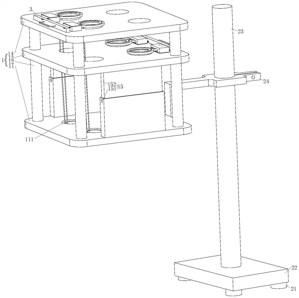
[0030] As a specific embodiment of the present invention, the support frame 2 includes a magnetic suction cup 21, a base 22, an adjustment rod 23 and a moving plate 24, and the magnetic suction cup 21 is fixed at four corners below the base 22;

[0031] The adjusting rod 23 is fixed above the base 22 , the moving plate 24 is provided with threaded holes, and the moving plate 24 is fixed to the adjusting rod 23 through a threaded connection.

[0032]Before fixing the test tube, the support frame 2 is placed on the metal table top, the magnetic suction cup 21 sucks the table top, the support frame 2 is fixed with the metal table top, and each of the four corners under the base 22 is provided with a magnetic suction cup 21 to increase the stability effect. The movable plate 24 is fixed on the lower end of the bottom plate 11, so the placing frame 1 moves with the movement of the movable plate 24, and the sliding connection is used to realize the up and down movement of the movable...


PUM


Abstract

The invention belongs to the technical field of placing racks, and particularly relates to a test tube placing rack which comprises a placing rack body, a supporting frame and a clamping device, the clamping device comprises a shell, a gear, a center rod, a clamping plate, a buffering device, a connecting rod, a guide rod, a sliding block, a spring and a pull rod, a handle is arranged above the pull rod, the pull rod is fixedly connected with the guide rod, the sliding block is fixedly connected into the shell, and the clamping plate is arranged on the supporting frame. A through groove is formed in the upper portion of the shell, a protrusion matched with the sliding groove is formed in the guide rod, the connecting rod and the guide rod are connected through the sliding groove and the protrusion, the connecting rod is fixedly connected with the clamping plate, the gear is fixedly connected with the clamping plate through the center rod, and the gear is installed away from the shell and fixed to the center rod. The spring is mounted on the guide rod above the shell and below the moving rod, the buffer device is arranged to stabilize the test tube, the clamping device is additionally arranged, clamping and loosening are achieved at the same time, convenience is provided for users, and clamping is firmer.

Description

technical field [0001] The invention belongs to the technical field of placing racks, and in particular relates to a test tube placing rack. Background technique [0002] The test tube is a commonly used instrument in the laboratory. It is used as a reaction container for a small amount of reagents. It is often necessary to use test tubes in the process of experiments or assays. When placing the test tubes, a rack is required. The existing test tube racks are easy to transport. Shaking, resulting in test tube collision and damage, resulting in certain economic losses. [0003] The existing common test tube placement rack cannot reliably fix the test tube. When the test tube placement rack is moved, the test tube will hit the outer wall of the test tube hole, resulting in collision and rupture of the test tube. SUMMARY OF THE INVENTION [0004] The purpose of the present invention is to provide a test tube placement rack. The specific problem to be solved by the present in...

Claims


Application Information

Patent Timeline
IPC IPC(8): B01L9/06
CPCB01L9/06B01L2200/02
Inventor 王佳奇杨凡范心宇
Owner 王佳奇
Why Eureka
Try Eureka