Guide rail locking device for railway vehicle door system

A locking device, a technology for rail vehicles, applied in the field of rail transit, and can solve problems such as lateral shaking of doors

Pending Publication Date: 2022-08-02
LIAONING PROVINCIAL COLLEGE OF COMM
View PDF2 Cites 0 Cited by
  • Summary
  • Abstract
  • Description
  • Claims
  • Application Information

AI Technical Summary

Problems solved by technology

[0004] The object of the present invention is to provide a guide rail locking device for a rail vehicle door system to solve the problem of lateral shaking of the door when the door is closed when the door is closed due to external forces such as road bumps

Method used


Image

  • Guide rail locking device for railway vehicle door system
  • Guide rail locking device for railway vehicle door system
  • Guide rail locking device for railway vehicle door system

Examples


Embodiment 1

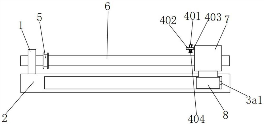
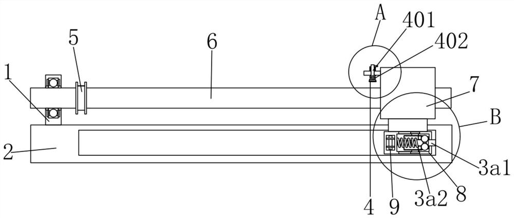
[0021] see figure 1 , image 3 , Figure 4 , Figure 5 and Image 6 , the present invention provides a technical solution: a guide rail locking device for a rail vehicle door system, comprising a vertical block 1 and a guide rail 2, the interior of the vertical block 1 is rotatably connected with a screw rod 6, and the middle of the screw rod 6 is connected to a circular The block 5 is fixedly connected, the right outer wall of the screw rod 6 is engaged with the connecting frame 7, the screw rod 6 is driven, the screw rod 6 drives the connecting frame 7 to move, the connecting frame 7 drives the slider 8 to move, and the bottom end of the connecting frame 7 is connected to the sliding block 7. The blocks 8 are fixedly connected, the inside of the slider 8 is provided with a locking device, and the left side of the connecting frame 7 is provided with a limiting device 4 .

[0022] The locking device includes a plunger 3a1, a conical cylinder 3a2, a ball 3a3, a sleeve block...

Embodiment 2

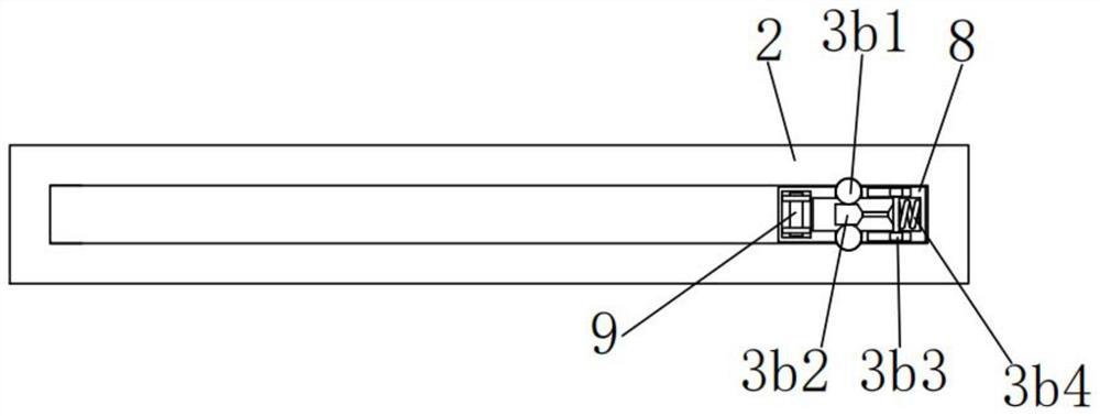
[0029] see figure 2, the present invention provides a technical solution: a guide rail locking device for a rail vehicle door system, wherein the locking device further comprises a rolling ball 3b1, a top rod 3b2, a sliding rod 3b3 and a second spring 3b4, two of the sliding rod 3b3 The end is slidably connected with the chute of the slider 8, the left end of the sliding rod 3b3 is fixedly connected with the ejector rod 3b2, the left outer wall of the ejector rod 3b3 is closely attached to the rolling ball 3b1, and the rolling ball 3b1 rolls into the concave on the right side of the ejector rod 3b3. In the groove, the elastic coefficient of the second spring 3b4 can be selected according to the actual use. The outer side of 3b1 is in close contact with the slider 8, the outer ends of the plurality of balls 3b1 are in close contact with the grooves of the guide rail 2, and the two ends of the second spring 3b4 are fixedly connected to the slider 8 and the sliding rod 3b3 respe...


PUM


Abstract

The guide rail locking device for the railway vehicle door system comprises a vertical block and a guide rail, the interior of the vertical block is rotationally connected with a lead screw, the middle of the lead screw is fixedly connected with a round block, the outer wall of the right side of the lead screw is meshed with a connecting frame, and the bottom end of the connecting frame is fixedly connected with a sliding block; a locking device is arranged in the sliding block, and a limiting device is arranged on the left side of the connecting frame. According to the guide rail locking device for the railway vehicle door system, through cooperation of a sliding block, an inserting rod, a circular ring, a first spring, a ball and a conical barrel, when the sliding block moves to the position where the inserting rod is inserted, a needle tip of the inserting rod pushes the circular ring and the first spring leftwards till the ball rolls into a groove of the inserting rod, and the first spring presses the ball and the circular ring rightwards; and the conical barrel is trumpet-shaped, so that the problem that the vehicle door swings transversely due to the influence of external force such as road bumping when the vehicle door is closed is solved.

Description

technical field [0001] The invention relates to the technical field of rail transportation, in particular to a guide rail locking device for a rail vehicle door system. Background technique [0002] The screw drive mechanism is widely used in rail vehicles, such as various vehicle doors, screen doors, civil doors, etc., and is equipped with locking and unlocking devices. At present, the commonly used passive locking devices for door systems include full passive locking, Screw passive locking, nut passive locking device. [0003] The rail locking device of the existing vehicle door system is affected by external forces such as road bumps when the vehicle door is closed, which causes the vehicle door to sway laterally, and the position of the vehicle door is easily unstable when the vehicle door is opened. SUMMARY OF THE INVENTION [0004] The purpose of the present invention is to provide a guide rail locking device for a rail vehicle door system, so as to solve the proble...

Claims


Application Information

Patent Timeline
Patent Type & Authority Applications(China)
IPC IPC(8): E05B83/36E05B79/10E05B81/08E05B81/14
CPCE05B83/363E05B79/10E05B81/08E05B81/14
Inventor 姜春霞郑海超孟博翔
Owner LIAONING PROVINCIAL COLLEGE OF COMM
Why Eureka
Try Eureka