Device for dehumidification

A heat exchanger and port technology, applied in applications, home appliances, household heating, etc., can solve problems such as temperature rise, user discomfort, and difficulty in meeting users' diverse dehumidification needs, so as to meet dehumidification needs and improve The effect of comfort

Pending Publication Date: 2022-08-05
HAIER SHENZHEN RES & DEV CO LTD +3
View PDF3 Cites 1 Cited by
  • Summary
  • Abstract
  • Description
  • Claims
  • Application Information

AI Technical Summary

Problems solved by technology

[0005] High indoor humidity usually occurs in hot summer, and the hot air blown by the dehumidifier after dehumidification will lead to an increase in the indoor ambient temperature, causing discomfort to the user, and it is difficult to meet the diverse dehumidification needs of the user

Method used


Image

  • Device for dehumidification
  • Device for dehumidification
  • Device for dehumidification

Examples


Embodiment Construction

[0022] In order to understand the features and technical contents of the embodiments of the present disclosure in more detail, the implementation of the embodiments of the present disclosure will be described in detail below with reference to the accompanying drawings, which are for reference only and are not intended to limit the embodiments of the present disclosure. In the following technical description, for the convenience of explanation, numerous details are provided to provide a thorough understanding of the disclosed embodiments. However, one or more embodiments may be practiced without these details. In other instances, well-known structures and devices may be shown simplified in order to simplify the drawings.

[0023] The terms "first", "second" and the like in the description and claims of the embodiments of the present disclosure and the above-mentioned drawings are used to distinguish similar objects, and are not necessarily used to describe a specific order or s...


PUM


Abstract

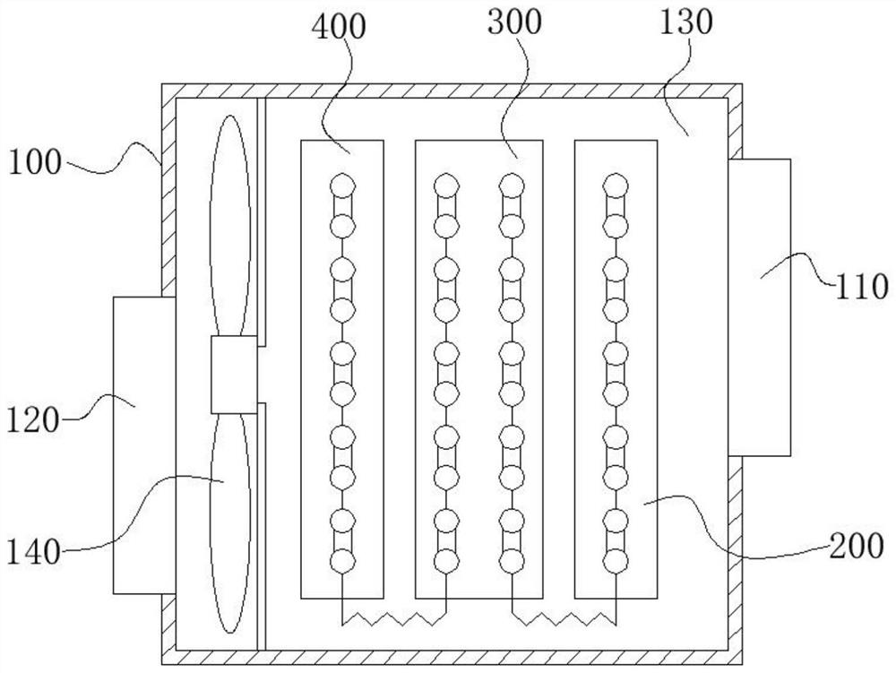
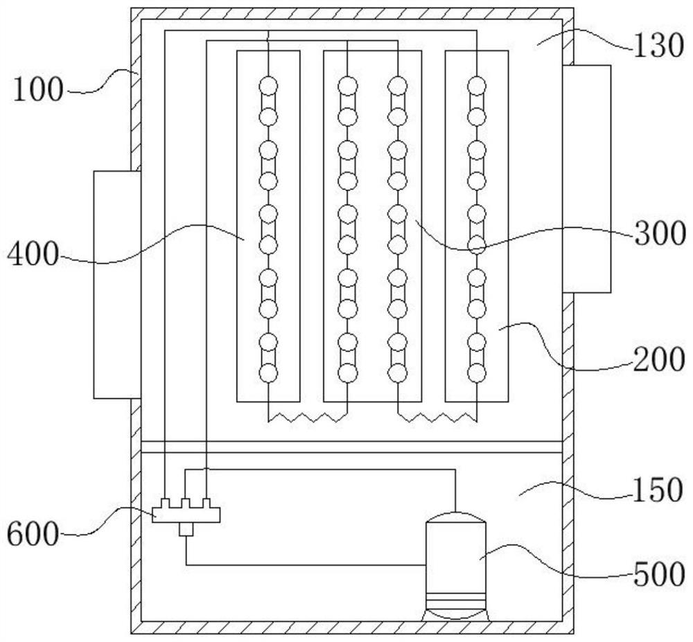
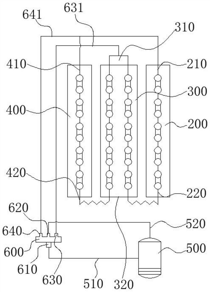
The invention relates to the technical field of dehumidification, and discloses a dehumidification device which comprises a shell, a first heat exchanger, a second heat exchanger and a third heat exchanger. The shell is provided with a dehumidification air inlet and a dehumidification air outlet; the first heat exchanger is arranged in the shell and located on the dehumidification air inlet side. The second heat exchanger is arranged on the leeward side of the first heat exchanger; the third heat exchanger is arranged on the leeward side of the second heat exchanger; airflow needing to be dehumidified flows into the shell through the dehumidification air inlet, sequentially flows through the first heat exchanger, the second heat exchanger and the third heat exchanger and then is blown out of the dehumidification air outlet. In the application, the states of the refrigerants flowing in the first heat exchanger, the second heat exchanger and the third heat exchanger can be selectively adjusted according to the dehumidification requirement of a user, namely, the temperature of the airflow blown out after dehumidification can be adjusted, the body feeling comfort of the user is improved, and the diversified dehumidification requirements of the user are met.

Description

technical field [0001] The present application relates to the technical field of dehumidification, and in particular, to a device for dehumidification. Background technique [0002] At present, with the improvement of the quality of life, the humidity requirements of the indoor environment are also increased. When the indoor humidity is high, the user's physical comfort will be poor, and the indoor stored items will also appear damp, which seriously affects the daily life of the user. Life. [0003] There is an indoor dehumidifier in the related art, an evaporator is set inside for cooling and dehumidification, the air flow after cooling and dehumidification is heated by heating elements such as electric heating wires or a condenser and then blown out, and the moisture in the air flow encounters the evaporator to cool down and condense, thereby Circulating and dehumidifying the airflow in the indoor environment. [0004] In the process of implementing the embodiments of th...

Claims


Application Information

Patent Timeline
Patent Type & Authority Applications(China)
IPC IPC(8): F24F3/14F24F3/153F24F13/30
CPCF24F3/14F24F3/153F24F13/30
Inventor 张新朝耿宝寒田雪梅闫长娟胡志刚孙帅辉
Owner HAIER SHENZHEN RES & DEV CO LTD
Why Eureka
Try Eureka