Optical system, image capturing module and terminal device

An optical system and optical axis technology, applied in the field of photography, can solve problems such as difficult to ensure driving safety performance and image quality needs to be improved

Active Publication Date: 2022-08-05
JIANGXI JINGCHAO OPTICAL CO LTD
View PDF4 Cites 0 Cited by
  • Summary
  • Abstract
  • Description
  • Claims
  • Application Information

AI Technical Summary

Problems solved by technology

However, the imaging quality of the current main field of view vehicle lens needs to be improved, and it is difficult to guarantee the driving safety performance

Method used


Image

  • Optical system, image capturing module and terminal device
  • Optical system, image capturing module and terminal device
  • Optical system, image capturing module and terminal device

Examples


no. 1 example

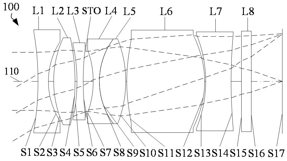
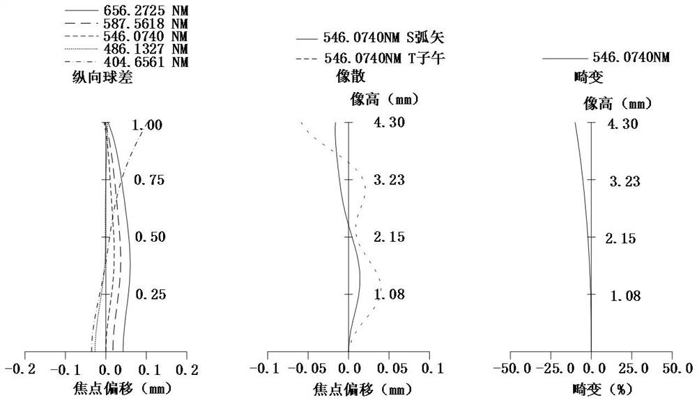
[0062] See figure 1 and figure 2 , figure 1 It is a schematic structural diagram of the optical system 100 in the first embodiment. The optical system 100 sequentially includes a first lens L1 with negative refractive power, a second lens L2 with positive refractive power, and a negative refractive power lens from the object side to the image side. The third lens L3, the diaphragm STO, the fourth lens L4 with negative refractive power, the fifth lens L5 with positive refractive power, the sixth lens L6 with positive refractive power, and the seventh lens L7 with negative refractive power, the The quadruple lens L4 and the fifth lens L5 are cemented. figure 2 From left to right are graphs of longitudinal spherical aberration, astigmatism, and distortion of the optical system 100 in the first embodiment, wherein the reference wavelength of the astigmatism graph and the distortion graph is 546.0740 nm, and other embodiments are the same.

[0063] The object side S1 of the fi...

no. 2 example

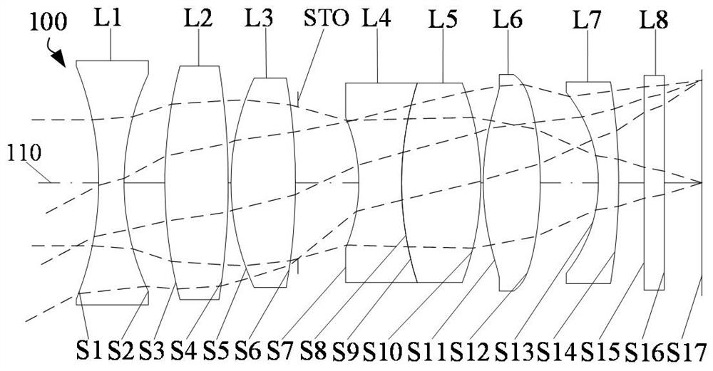
[0085] See image 3 and Figure 4 , image 3 It is a schematic structural diagram of the optical system 100 in the second embodiment. The optical system 100 sequentially includes a first lens L1 with a negative refractive power, a second lens L2 with a positive refractive power, and a lens with a positive refractive power from the object side to the image side. The third lens L3, the diaphragm STO, the fourth lens L4 with negative refractive power, the fifth lens L5 with positive refractive power, the sixth lens L6 with positive refractive power, and the seventh lens L7 with negative refractive power, the th The quadruple lens L4 and the fifth lens L5 are cemented. Figure 4 From left to right are graphs of longitudinal spherical aberration, astigmatism and distortion of the optical system 100 in the second embodiment.

[0086] The object side S1 of the first lens L1 is concave at the near optical axis 110, and the image side S2 is concave at the near optical axis 110;

[...

no. 3 example

[0103] See Figure 5 and Image 6 , Figure 5 It is a schematic structural diagram of the optical system 100 in the third embodiment. The optical system 100 sequentially includes a first lens L1 with negative refractive power, a second lens L2 with positive refractive power, and a lens with positive refractive power from the object side to the image side. The third lens L3, the diaphragm STO, the fourth lens L4 with negative refractive power, the fifth lens L5 with positive refractive power, the sixth lens L6 with positive refractive power, and the seventh lens L7 with negative refractive power, the th The quadruple lens L4 and the fifth lens L5 are cemented. Image 6 From left to right are graphs of longitudinal spherical aberration, astigmatism and distortion of the optical system 100 in the third embodiment.

[0104] The object side S1 of the first lens L1 is concave at the near optical axis 110, and the image side S2 is concave at the near optical axis 110;

[0105] Th...


PUM


Abstract

The invention relates to an optical system, an image capturing module and terminal equipment. The optical system includes a first lens element with negative refractive power, an object-side surface being concave in a paraxial region thereof, and an image-side surface being concave in a paraxial region thereof; a second lens element with positive refractive power having an object-side surface being convex in a paraxial region thereof; a third lens element with refractive power; a fourth lens element with negative refractive power having an object-side surface being concave in a paraxial region thereof and an image-side surface being concave in a paraxial region thereof; a fifth lens element with positive refractive power having an object-side surface being convex in a paraxial region thereof and an image-side surface being convex in a paraxial region thereof; a sixth lens element with positive refractive power having an object-side surface being convex in a paraxial region thereof and an image-side surface being convex in a paraxial region thereof; a seventh lens element with negative refractive power having an object-side surface being concave in a paraxial region thereof; the optical system satisfies that Rs11 / Rs12 is greater than or equal to 1 and less than or equal to 4.5. The optical system has a large visual angle and good imaging quality.

Description

technical field [0001] The invention relates to the field of imaging, in particular to an optical system, an imaging module and a terminal device. Background technique [0002] In recent years, with the continuous improvement of the country's requirements for road traffic safety and automobile safety, the degree of automobile intelligence has also continued to improve. As a result, the industry has higher and higher requirements for the optical performance of vehicle lenses. Cars usually include three vehicle-mounted lenses: a front-view wide-view lens, a main-view lens and a narrow-view lens. The three vehicle-mounted lenses together take into account the wide viewing angle in front of the vehicle and the image capture of distant objects. Among them, the main view vehicle lens can cover most traffic scenes, so the role of the main view vehicle lens in the industry is becoming more and more significant. However, the imaging quality of the current main view vehicle lens stil...

Claims


Application Information

Patent Timeline
IPC IPC(8): G02B13/18G02B13/06
CPCG02B13/0045G02B13/06
Inventor 乐宇明兰宾利朱志鹏
Owner JIANGXI JINGCHAO OPTICAL CO LTD
Why Eureka
Try Eureka