Optical lens, camera module and electronic equipment

An optical lens and lens technology, applied in optics, optical components, instruments, etc., can solve problems such as the inability to meet the miniaturization design of optical lenses, the inability to meet customer shooting needs, the small amount of light entering the optical lens, etc., to shorten the total optical length, meet the Miniaturized design, the effect of improving the field of view

Active Publication Date: 2021-10-29
NANCHANG OUFEI BIOLOGICAL IDENTIFICATION TECH
View PDF9 Cites 2 Cited by
  • Summary
  • Abstract
  • Description
  • Claims
  • Application Information

AI Technical Summary

Problems solved by technology

However, if a design with a smaller aperture is adopted to improve the imaging distortion problem, the amount of light entering the optical lens per unit time will be small, resulting in a poor imaging effect of the optical lens in a dark environment, which cannot satisfy customers. Shooting requirements in dark light environments; if the total length of the optical lens is increased to change the distortion of the imaging, it will not be able to meet the needs of the miniaturized design of the optical lens

Method used


Image

  • Optical lens, camera module and electronic equipment
  • Optical lens, camera module and electronic equipment
  • Optical lens, camera module and electronic equipment

Examples


no. 1 example

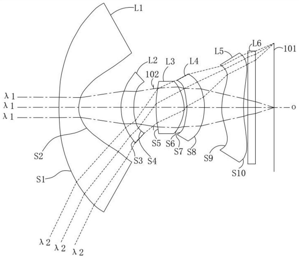
[0068] see figure 1 , the optical lens 100 includes a first lens L1, a second lens L2, a diaphragm 102, a third lens L3, a fourth lens L4, a fifth lens L5 and a filter arranged in sequence from the object side to the image side along the optical axis o L6. For the materials of the first lens L1 , the second lens L2 , the third lens L3 , the fourth lens L4 and the fifth lens L5 , please refer to the description of the above-mentioned specific embodiments, and details are not repeated here.

[0069] Further, the first lens L1 has negative refractive power, the second lens L2 has positive refractive power, the third lens L3 has positive refractive power, the fourth lens L4 has negative refractive power, and the fifth lens L5 has positive refractive power.

[0070] Furthermore, the object side S1 and the image side S2 of the first lens L1 are respectively convex and concave at the near optical axis o. The object side S3 and the image side S4 of the second lens L2 are respectivel...

no. 2 example

[0093] see Figure 4 , Figure 4 It is a schematic structural diagram of the optical lens 100 according to the second embodiment of the present application, and shows the optical paths of the first light beam λ1 and the second light beam λ2 . The optical lens 100 includes a first lens L1, a second lens L2, a diaphragm 102, a third lens L3, a fourth lens L4, a fifth lens L5 and a filter L6 arranged in sequence from the object side to the image side along the optical axis o . For the materials of the first lens L1 , the second lens L2 , the third lens L3 , the fourth lens L4 and the fifth lens L5 , please refer to the description of the above-mentioned specific embodiments, and details are not repeated here.

[0094] Further, in the second embodiment, the refractive power of each lens and the surface shape at the near optical axis o are respectively the same as the refractive power of each lens and its surface shape at the near optical axis o in the first embodiment .

[009...

no. 3 example

[0110] see Figure 7 , Figure 7 It is a schematic structural diagram of the optical lens 100 according to the third embodiment of the present application. The optical lens 100 includes a first lens L1, a second lens L2, a diaphragm 102, a third lens L3, a fourth lens L4, a fifth lens L5 and a filter L6 arranged in sequence from the object side to the image side along the optical axis o . For the materials of the first lens L1 , the second lens L2 , the third lens L3 , the fourth lens L4 and the fifth lens L5 , please refer to the description of the above-mentioned specific embodiments, and details are not repeated here.

[0111] Further, in the third embodiment, the refractive power of each lens and the surface shape at the near optical axis o are respectively the same as the refractive power of each lens and its surface shape at the near optical axis o in the first embodiment .

[0112] In the third embodiment, with the aperture number Fno=1.45 of the optical lens 100, t...


PUM


Abstract

The invention discloses an optical lens, a camera module and electronic equipment. The optical lens comprises a first lens, a second lens, a third lens, a fourth lens and a fifth lens which are sequentially arranged from an object side to an image side along an optical axis. The first lens with negative refractive power has a convex object-side surface and a concave image-side surface. The second lens with positive refractive power has a convex object-side surface and a concave image-side surface. The third lens with positive refractive power has a convex object-side surface and a convex image-side surface. The fourth lens with negative refractive power has a concave object-side surface and a convex image-side surface. The fifth lens with positive refractive power has an object-side surface being convex in a paraxial region thereof. The optical lens meets the following relational expression: 45 deg < HFOV/Fno < 49 deg, HFOV is half of the maximum field angle of the optical lens, and Fno is the aperture number of the optical lens; thus, the optical lens has a large view angle and also has a large aperture number to enhance the imaging effect of the optical lens in a dark light environment.

Description

technical field [0001] The invention relates to the technical field of optical imaging, in particular to an optical lens, a camera module and electronic equipment. Background technique [0002] At present, with the development of camera technology, optical lenses with wide-angle shooting functions are becoming more and more popular. In related technologies, the aperture setting of an optical lens with a larger viewing angle is smaller or the total length of the optical lens is increased to improve distortion. phenomenon, thereby improving image quality. However, if a design with a smaller aperture is adopted to improve the imaging distortion problem, the amount of light entering the optical lens per unit time will be small, resulting in a poor imaging effect of the optical lens in a dark environment, which cannot satisfy customers. Shooting needs in dark light environments; if the total length of the optical lens is increased to change the distortion problem of imaging, it ...

Claims


Application Information

Patent Timeline
Patent Type & Authority Applications(China)
IPC IPC(8): G02B13/00G02B13/18G02B13/06
CPCG02B13/0045G02B13/18G02B13/06
Inventor 不公告发明人
Owner NANCHANG OUFEI BIOLOGICAL IDENTIFICATION TECH
Why Eureka
Try Eureka