
Display base plate and preparation method thereof as well as display device

A technology for display substrates and substrate substrates, applied in the directions of identification devices, optics, lenses, etc., can solve the problems of poor display, small light-emitting angle of subwavelength grating polarizer, and small viewing angle of display devices, etc. The effect of viewing angle range

Inactive Publication Date: 2016-03-30
BOE TECH GRP CO LTD
View PDF10 Cites 16 Cited by
  • Summary
  • Abstract
  • Description
  • Claims
  • Application Information

AI Technical Summary

Problems solved by technology

[0005] However, when the above-mentioned color filter based on the subwavelength grating polarizer is applied to a display device, since the light emitted by the backlight is vertically incident on the subwavelength grating polarizer after passing through the optical film, it is polarized by the subwavelength grating The red, green, and blue light filtered out by the filter are also emitted vertically, resulting in a small viewing angle of light from the subwavelength grating polarizer, and the subwavelength polarizer seen by the viewer at the position corresponding to the center of the display device and other positions off the center. The light wavelengths filtered out by the grating polarizer are different, so that the display device using the sub-wavelength grating polarizer to achieve color filtering has the defect of a small viewing angle, resulting in poor display

Method used


Image

  • Display base plate and preparation method thereof as well as display device
  • Display base plate and preparation method thereof as well as display device
  • Display base plate and preparation method thereof as well as display device

Examples


Embodiment Construction

[0037] The following will clearly and completely describe the technical solutions in the embodiments of the present invention with reference to the accompanying drawings in the embodiments of the present invention. Obviously, the described embodiments are only some, not all, embodiments of the present invention. Based on the embodiments of the present invention, all other embodiments obtained by persons of ordinary skill in the art without making creative efforts belong to the protection scope of the present invention.

[0038]It should be noted that all terms (including technical and scientific terms) used in the embodiments of the present invention have the same meanings as commonly understood by those of ordinary skill in the art to which the present invention belongs. It should also be understood that terms such as those defined in common dictionaries should be interpreted as having meanings consistent with their meanings in the context of the relevant technology, and shoul...


PUM

PropertyMeasurementUnit
Heightaaaaaaaaaa

Abstract

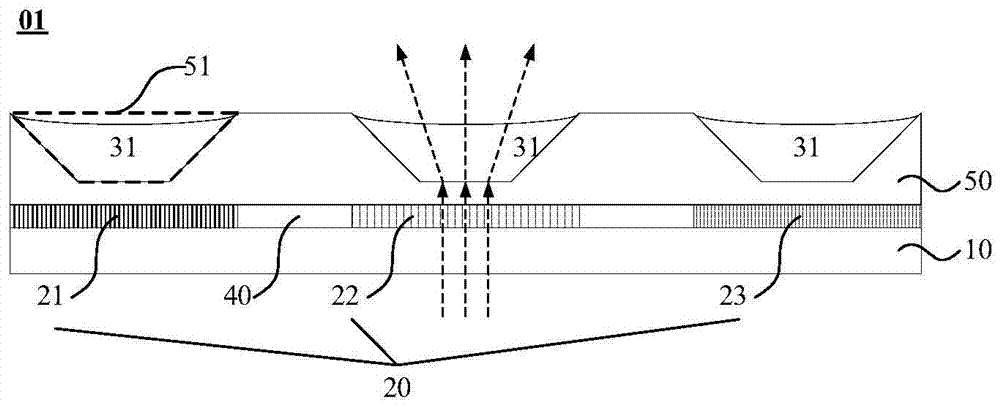
The embodiment of the invention provides a display base plate and a preparation method thereof as well as a display device and relates to the technical field of display, aiming at solving a view angle problem caused by the fact that the display device adopts optical gratings to realize color filtering. The display base plate comprises a colored filtering layer arranged on a substrate base plate; the colored filtering layer comprises a plurality of types of color filtering units which are arrayed in a matrix manner; each of the plurality of types of color filtering units is at least composed of a first optical grating, a second optical grating and a third optical grating; the three optical gratings are used for carrying out light filtering on incident light emitted to the display base plate respectively to obtain light with three base colors; the display base plate further comprises a lens structure; aiming at a region corresponding to any optical grating, the lens structure is used for enabling one part of light emitted from the display base plate to diverge relative to the incident light. The preparation of the display base plate and the display device comprising the display base plate is realized.

Description

technical field [0001] The invention relates to the field of display technology, in particular to a display substrate, a preparation method thereof, and a display device. Background technique [0002] The grating consists of strips of metal spaced at equal intervals. Such as figure 1 As shown, the height of the grating (that is, the thickness of the strip metal) is h, the width of the ridge of the grating (that is, the width of the strip metal) is w, and the period p of the grating is determined by the width of the ridge w and the distance between two adjacent strip metals. The spacing constitutes, and the duty ratio F is equal to w / p. [0003] When the period p has a size equivalent to or smaller than the wavelength of visible light, the reflectivity, transmittance, polarization characteristics, and spectral characteristics of the grating show completely different characteristics from conventional diffractive optical elements. At this time, the grating is called Subwavel...

Claims


Application Information

Patent Timeline
IPC IPC(8): G09F9/30G02B3/00
CPCG09F9/30G02B3/0006
Inventor 姚琪曹占锋张锋何晓龙李正亮关峰高锦成张伟
Owner BOE TECH GRP CO LTD
Learn More