Locking device

A lock tongue and stopper technology, applied to locks. field, which can solve problems such as low reliability and weak insurance institutions’ ability to bear

Pending Publication Date: 2022-08-09
中山市摩根金属制品有限公司
View PDF0 Cites 0 Cited by
  • Summary
  • Abstract
  • Description
  • Claims
  • Application Information

AI Technical Summary

Problems solved by technology

However, the existing insurance institutions have weak bearing capacity, and the reliability of the use of locks is low

Method used


Image

  • Locking device
  • Locking device
  • Locking device

Examples


Embodiment Construction

[0024] Embodiments of the present invention are described in detail below, examples of which are illustrated in the accompanying drawings, wherein the same or similar reference numerals refer to the same or similar elements or elements having the same or similar functions throughout. The embodiments described below with reference to the accompanying drawings are exemplary, only used to explain the present invention, and should not be construed as a limitation of the present invention.

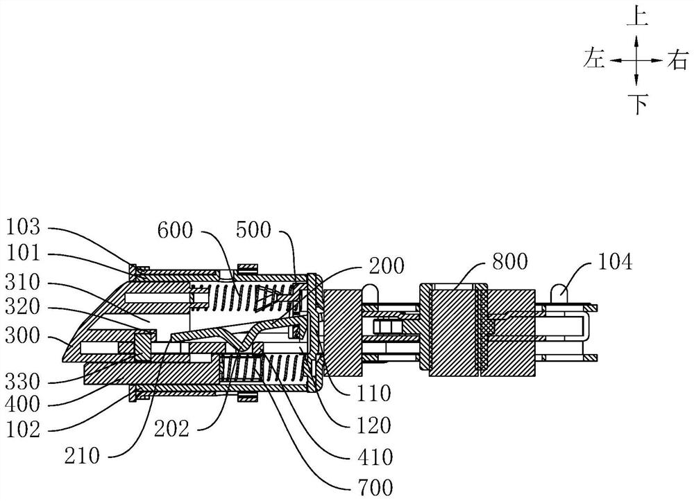
[0025] In the description of the present invention, it should be understood that orientation descriptions are involved, such as the terms "upper", "lower", "front", "rear", "left", "right", "vertical", "horizontal" "," "top", "bottom", "inside", "outside" and other indicated orientations or positional relationships are based on the orientations or positional relationships shown in the accompanying drawings, and are only for the convenience of describing the present invention and simplifying the ...


PUM


Abstract

The invention discloses a lock bar. The lock bar comprises a main body; the blocking piece is movably arranged in the main body, the blocking piece can swing up and down relative to the main body, and the blocking piece is provided with a first abutting surface; the spring bolt is arranged on the main body in a telescopic mode, the spring bolt is provided with an avoiding part facing the blocking piece and a second abutting face, and the avoiding part is located above the second abutting face; the linkage piece is telescopically arranged on the main body, and the linkage piece is used for driving the blocking piece to swing; after the spring bolt extends out relative to the main body, the linkage piece can be subjected to external force to link the blocking piece to move, so that the first abutting face can swing to be opposite to the second abutting face. According to the lock bar of the structure, the blocking piece can be in plane contact with the spring bolt in the swinging process, the stress contact area of the blocking piece and the spring bolt is increased, then the bearing capacity of the blocking piece for blocking movement of the spring bolt is improved, and the service life of the lock bar is guaranteed.

Description

technical field [0001] The invention relates to the technical field of locks, in particular to a lock. Background technique [0002] At present, the lock is achieved by locking the door by engaging the lock tongue with the groove on the door frame. In order to prevent the lock tongue from exiting the groove under external force, the lock will set up a safety mechanism to ensure the door locking effect. However, the existing insurance institutions have weak bearing capacity, and the reliability of the use of locks is low. SUMMARY OF THE INVENTION [0003] The present invention aims to solve at least one of the technical problems existing in the prior art. To this end, the present invention proposes a lock blade, through which the blocking member can form a plane contact with the lock tongue during the swinging process, which increases the force contact area of ​​the two, thereby improving the resistance of the blocking member to hinder the movement of the lock tongue. , ...

Claims


Application Information

Patent Timeline
Patent Type & Authority Applications(China)
IPC IPC(8): E05B15/10
CPCE05B15/101
Inventor 何亮
Owner 中山市摩根金属制品有限公司
Why Eureka
Try Eureka