Complex sound exciter drive circuit and portable information terminal

A composite sound and exciter technology, applied in transducer circuits, telephone communications, electromagnetic audible signals, etc., can solve the problems of cost increase, large vibration diffusion, etc.

Inactive Publication Date: 2004-09-22
NEC CORP
View PDF1 Cites 0 Cited by
  • Summary
  • Abstract
  • Description
  • Claims
  • Application Information

AI Technical Summary

Problems solved by technology

[0006] Therefore, if Figure 12 shown in Figure 12 In the configuration shown, the signal generator 1 generates an electrical signal of a predetermined frequency, the amplifier 2 amplifies the electrical signal, and the amplified signal is input to the composite acoustic exciter 3 to generate sound or vibration, however, there is a problem of generating Large spread of vibration
Specifically, in order to search for the resonant frequency f of each acoustic exciter OReal A complicated auto-tracking circuit must be installed, resulting in an increase in cost

Method used


Image

  • Complex sound exciter drive circuit and portable information terminal
  • Complex sound exciter drive circuit and portable information terminal
  • Complex sound exciter drive circuit and portable information terminal

Examples


no. 1 example

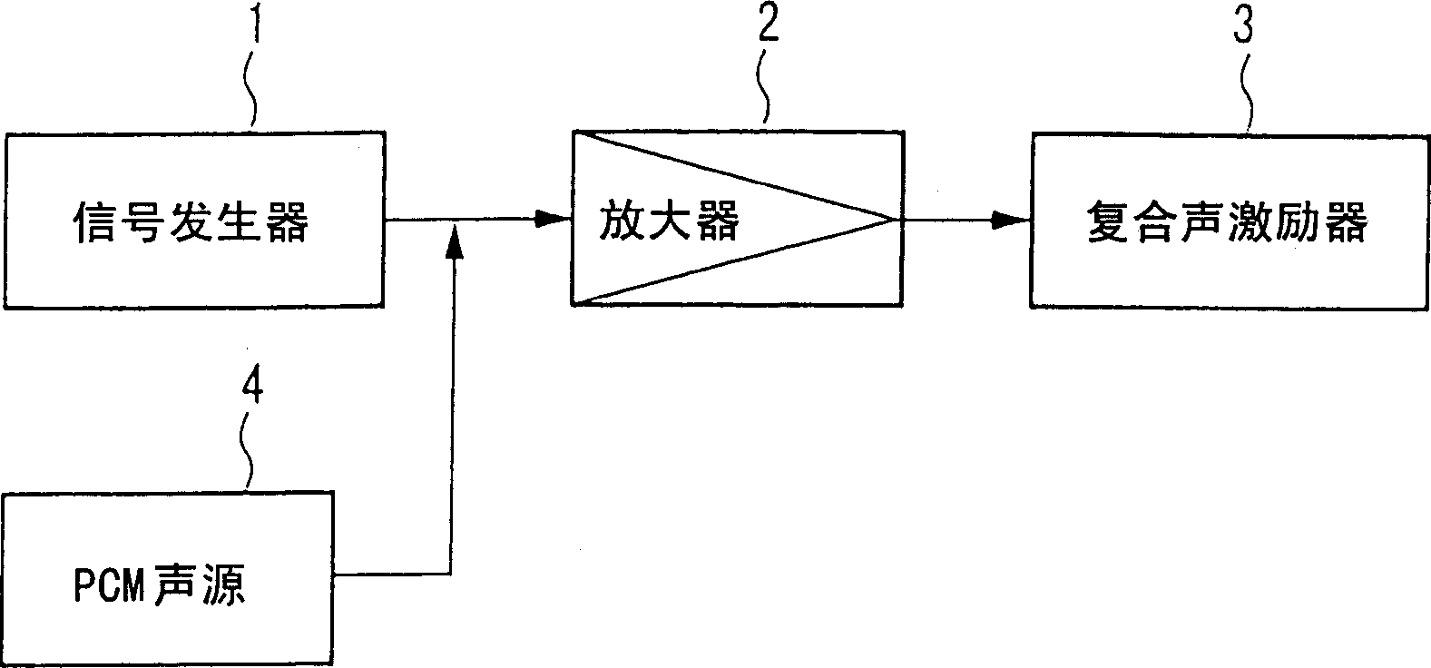
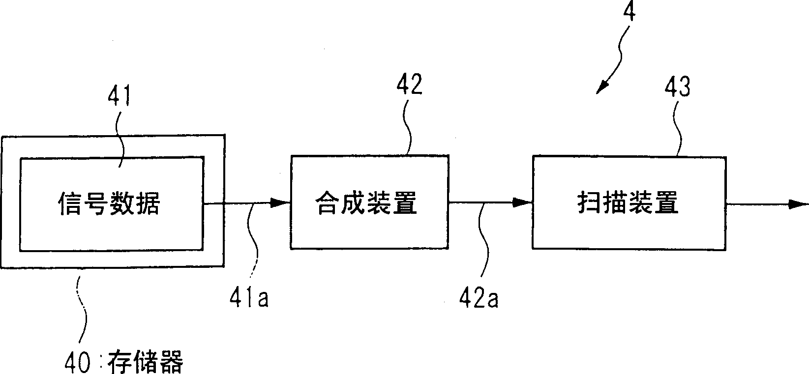
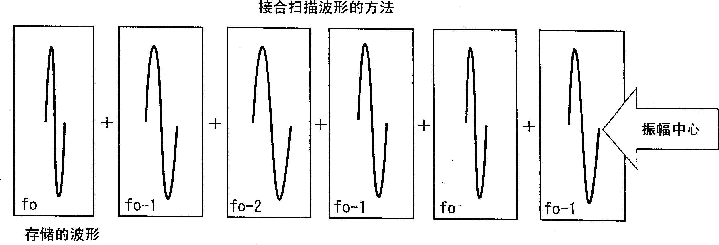
[0031] Specifically, FIG. 1 shows a block diagram of the configuration of the first embodiment of the present invention. In the first embodiment, the signal generator 1 generates an audio signal. In the PCM sound source (vibration signal generator) 4, a plurality of sine waves having a predetermined number of cycles at predetermined frequency intervals are stored in a memory in advance, and then spliced ​​together and output. The signal generator 1 and the PCM sound source 4 form a drive signal circuit. The amplifier 2 amplifies the driving signal from the signal generator 1 and the PCM sound source 4 , and outputs the amplified signal to the composite acoustic exciter 3 . The composite acoustic exciter 3 generates sound according to the output of the signal generator 1 and generates vibration according to the output of the PCM sound source 4 .

[0032] Therefore, in this embodiment of the present invention, with regard to the call notification operation when the portable in...

no. 2 example

[0046] Figure 9 A second embodiment of the present invention is shown. In this embodiment, the variable voltage generator 5 and the voltage-controlled oscillator 6 are provided at the position of the PCM sound source 4 shown in FIG. 1 . Contrary to the use of the PCM sound source 4 in which a plurality of sine wave waveforms having a prescribed number of cycles at prescribed frequency intervals are converted, in the second embodiment, by changing the voltage of the voltage-controlled oscillator 6 The voltage is controlled, and the oscillation frequency is controlled by the variable voltage generator 5, thereby generating a driving waveform. In this embodiment, when generating the driving waveform, the frequency sweep range includes the actual resonant frequency f 0 In any frequency band within the range, this range is continuously scanned.

[0047] As described above, the second embodiment of the present invention is a signal generating circuit for a composite acoustic exc...


PUM


Abstract

In a signal generation circuit for a compound acoustic actuator that generates a sound and a vibration in response to a frequency of a signal input to the compound acoustic actuator, the signal generation circuit comprising a plurality of signal data stored in a memory to generate a plurality of signals having mutually different frequencies, the plurality of signals at least including a signal, a frequency of which is equal to a resonant frequency causing the compound acoustic actuator to generate the vibration, a synthesizing means to synthesize a plurality of drive signals in accordance with the plurality of signal data so as to cause the compound acoustic actuator to generate the vibration, and a sweeping means to sweep the plurality of drive signals, repeatedly.

Description

technical field [0001] The present invention relates to a composite acoustic exciter drive circuit suitable for use in portable information terminals where there is a variation in the resonant frequency of the composite acoustic exciter. Background technique [0002] Composite acoustic exciters use the working principle of dynamic speakers to generate vibration and sound, and are used in portable information terminals such as cellular phones to generate sound or vibration when a call is received. The composite acoustic exciter has a resonant frequency corresponding to sound and a resonant frequency corresponding to vibration. Generally, when a signal whose frequency is equal to the low resonant frequency is input, the composite acoustic exciter works as a vibrating body, and when a signal whose frequency is equal to a high frequency is input, the composite acoustic exciter works as an acoustic generator. In this case, both vibration and sound are used to notify the user tha...

Claims


Application Information

Patent Timeline
Patent Type & Authority Patents(China)
IPC IPC(8): H04R1/00B06B1/04G08B3/10G08B6/00H02N2/06H04M1/00H04R3/00
CPCG08B6/00G08B3/10
Inventor 高桥智惠美
Owner NEC CORP
Why Eureka
Try Eureka