Developing device, image forming device, and developer carrier for developing device

A developing device and developer technology, applied in the direction of electric recording process applying charge pattern, equipment and instrument of electric recording process applying charge pattern, etc. bad effect

Active Publication Date: 2019-10-11
KYOCERA DOCUMENT SOLUTIONS INC
View PDF8 Cites 0 Cited by
  • Summary
  • Abstract
  • Description
  • Claims
  • Application Information

AI Technical Summary

Problems solved by technology

However, plastic magnets are expensive compared to rubber magnets

Method used


Image

  • Developing device, image forming device, and developer carrier for developing device
  • Developing device, image forming device, and developer carrier for developing device
  • Developing device, image forming device, and developer carrier for developing device

Examples


Embodiment 1

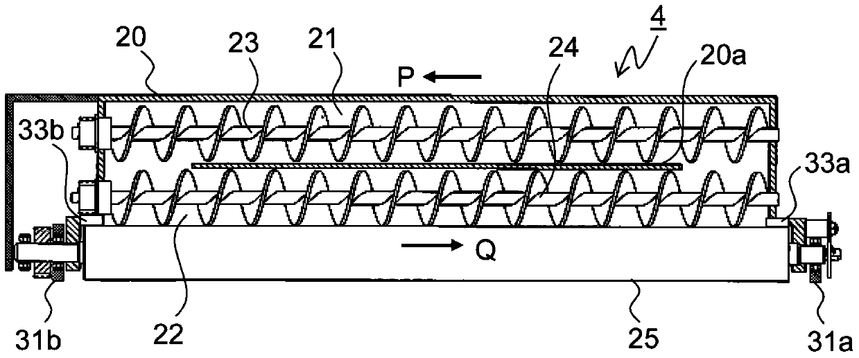
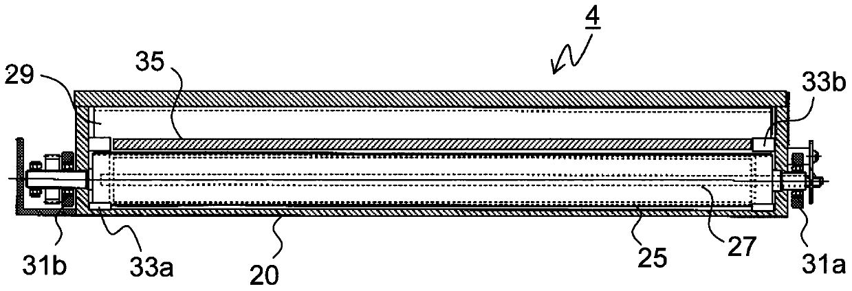
[0059] The relationship between the arrangement of plastic magnets and rubber magnets used as the magnetic poles of the fixed magnet 27 and the amount of deformation of the rotating shaft 27 e was investigated. As a test method, the developing device 4 of the first embodiment, the developing device 4 of the second embodiment, and the developing device 4 of the comparative example were produced. The developing device 4 of the first embodiment (invention 1) was as follows: Figure 4 As shown, the S1 poles 27a and S2 poles 27c using plastic magnets of the same shape and the N1 poles 27b and N2 poles 27d using rubber magnets of the same shape are respectively arranged axisymmetrically with respect to the rotation axis 27e. Device 4 (the present invention two) such as Image 6 As shown in FIG. Figure 9 As shown, only the S2 pole 27c uses a plastic magnet, and the S1 pole 27a, N1 pole 27b, and N2 pole 27d use rubber magnets.

[0060] In the present invention one, the magnet heigh...


PUM


Abstract

The present invention provides a developing device, an image forming device including the developing device, and a developer carrier used in the developing device. The developing device includes a frame body, a developer carrier, and a magnet member. The frame accommodates a magnetic developer. The developer carrier is rotatably supported by the frame body, and the outer peripheral surface is used to carry the developer. The magnet member has a rotation shaft fixed to the inside of the developer carrier, and a plurality of developer carrier side magnetic poles fixed to the circumference of the rotation shaft. As for the magnet member, an even number of magnetic poles on the developer carrier side are formed by plastic magnets, and one or more other magnetic poles are formed by rubber magnets, and more than one pair of plastic magnets facing each other across the rotating shaft have the same shape and are opposite to each other. The axis of rotation is fixed axisymmetrically.

Description

technical field [0001] The present invention relates to image forming apparatuses such as copiers, printers, and facsimiles, developing devices used therein, and developer carriers, and more particularly to a method for suppressing deformation of fixed magnets arranged in the developer carriers. Background technique [0002] Conventionally, as a developing method of an image forming apparatus using an electrophotographic method, a powder developer is mainly used, and the usual process is to visualize an electrostatic latent image formed on an image carrier such as a photosensitive drum with the developer, and then visualize the visible image ( After the toner image) is transferred to the recording medium, a fixing process is performed. [0003] Developers are roughly divided into two-component developers consisting of toner and magnetic carriers and one-component developers consisting only of non-magnetic or magnetic toners. As a development method using two-component develo...

Claims


Application Information

Patent Timeline
Patent Type & Authority Patents(China)
IPC IPC(8): G03G15/09
CPCG03G15/0928G03G15/0812G03G15/0914G03G15/0942G03G15/0921
Inventor 丹村荣司
Owner KYOCERA DOCUMENT SOLUTIONS INC
Why Eureka
Try Eureka