Electric motor rotor, electric motor, air conditioner, and production method for electric motor rotor

A manufacturing method and motor technology, applied in the direction of electric components, electrical components, electromechanical devices, etc., can solve the problems of cost increase, insulation part detachment, etc., and achieve the effect of preventing shaft current, preventing abnormal sound, and inhibiting electrical corrosion

Active Publication Date: 2014-12-24
MITSUBISHI ELECTRIC CORP
View PDF6 Cites 0 Cited by
  • Summary
  • Abstract
  • Description
  • Claims
  • Application Information

AI Technical Summary

Problems solved by technology

[0010] However, in the electric mechanism of the above-mentioned Patent Document 1, a concave portion is provided on the side of the bearing bracket that contacts the insulator, a convex portion corresponding to the concave portion of the bearing bracket is provided on the insulator, and the convex portion of the insulator is Fitted and fixed to the recessed part of the bearing bracket, although the structure is simple and the assembly is easy, on the contrary, there is a problem that the insulator is easily detached from the bearing bracket
[0011] Furthermore, in the anti-galvanic rolling bearing of Patent Document 2, the interface between the peripheral surface of the fitting surface of the inner ring or the peripheral surface of the fitting surface of the outer ring and the chamfered portion forms a gentle tapered surface or an arc with a large radius of curvature. surface, and an insulating coating of an inorganic compound formed by sputtering is formed on at least one of the fitting surfaces, so there is a problem of cost increase

Method used


Image

  • Electric motor rotor, electric motor, air conditioner, and production method for electric motor rotor
  • Electric motor rotor, electric motor, air conditioner, and production method for electric motor rotor
  • Electric motor rotor, electric motor, air conditioner, and production method for electric motor rotor

Examples


Embodiment approach 1

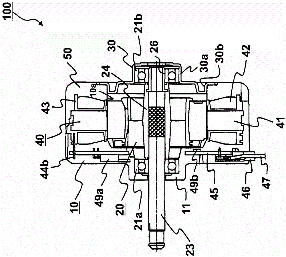
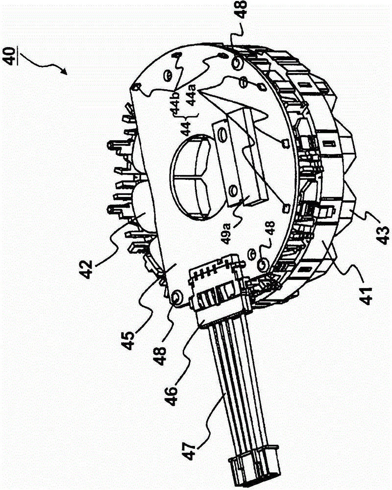
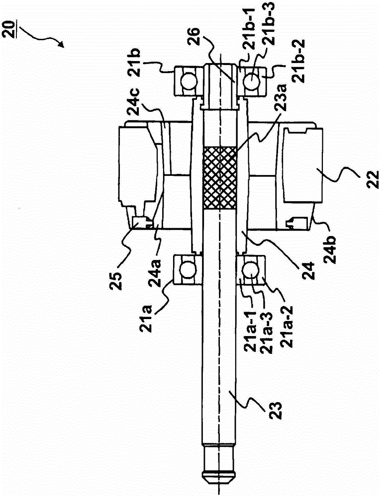
[0033] Figure 1 to Figure 14 is a diagram showing Embodiment 1, figure 1 is a cross-sectional view of the motor 100, figure 2 is a perspective view of the stator 40, image 3 is a cross-sectional view of the rotor 20, Figure 4 is an enlarged sectional view of the opposite-to-load side end of the shaft 23, Figure 5 is a diagram showing the insulating sleeve 26 ((a) is a front view, (b) is a side view), Image 6 It is a figure which shows the resin magnet 22 of a rotor ((a) is a left side view, (b) is A-A cross-sectional view of (a), (c) is a right side view), Figure 7 It is a diagram showing the resin magnet 25 for position detection ((a) is a left side view, (b) is a front view, and (c) is an enlarged view of part A of (b)), Figure 8 is a cross-sectional view of the rotor 20 of Modification 1, Figure 9 is a cross-sectional view of the rotor 20 of Modification 2, Figure 10 is a front view of the insulating sleeve 26 used in the rotor 20 of Modification 2, Figur...

Embodiment approach 2

[0140] Figure 15 It is a figure which shows Embodiment 2, and is a structural figure of the air conditioner 300. FIG.

[0141] The air conditioner 300 includes an indoor unit 310 and an outdoor unit 320 connected to the indoor unit 310 . An indoor unit blower (not shown) is mounted on the indoor unit 310 , and an outdoor unit blower 330 is mounted on the outdoor unit 320 .

[0142] Furthermore, the air blower 330 for an outdoor unit and the air blower for an indoor unit are provided with the electric motor 100 of Embodiment 1 mentioned above as a drive source.

[0143] The durability of the air conditioner 300 is improved by mounting the electric motor 100 according to Embodiment 1 on the outdoor unit blower 330 and the indoor unit blower which are main components of the air conditioner 300 .


PUM


Abstract

An electric motor rotor is provided in which an insulating sleeve applied to a shaft for performing insulation between a roller bearing and a shaft to suppress electrolytic corrosion of a bearing can be surely fixed by a simple method. In an electric motor rotor 20 according to the present invention, a rotor resin magnet 22 and a shaft 23 are integrated by a resin section 24 and a roller bearing is arranged in the shaft 23. An insulating sleeve 26 is provided between the shaft 23 and the roller bearing, and the insulating sleeve 26 is integrated and fixed by the resin section 24.

Description

technical field [0001] The present invention relates to a rotor of an electric motor using a rolling bearing, and relates to a rotor of an electric motor suitable for an electric motor driven by an inverter. Furthermore, it relates to an electric motor using the rotor of the electric motor, a method of manufacturing the rotor of the electric motor, and an air conditioner equipped with the electric motor. Background technique [0002] Conventionally, when an inverter is used to drive a motor, the carrier frequency of the inverter has been set high for the purpose of reducing noise of the motor accompanying switching of transistors in a power circuit. As the carrier frequency is set higher, the shaft voltage generated on the shaft of the motor due to high-frequency induction increases, and the potential difference between the inner ring and outer ring of the rolling bearing supporting the shaft increases, so the current flow is easy. flow to rolling bearings. The current flo...

Claims


Application Information

Patent Timeline
Patent Type & Authority Patents(China)
IPC IPC(8): H02K1/27
CPCH02K1/278H02K11/0021H02K15/10H02K11/215H02K1/2733H02K5/1732
Inventor 川久保守山本峰雄石井博幸山崎东吾麻生洋树
Owner MITSUBISHI ELECTRIC CORP
Why Eureka
Try Eureka