Motor

A technology of motors and armatures, applied in the field of motors, can solve problems such as poor connection and weakened contact

Active Publication Date: 2009-02-11
DENSO CORP
View PDF9 Cites 0 Cited by
  • Summary
  • Abstract
  • Description
  • Claims
  • Application Information

AI Technical Summary

Problems solved by technology

Therefore, the posture change of the brush holder device is particularly easy to produce, which may cause the problem
In addition, with this posture change, the contact between the male connection terminal on the plate cover side and the female connection terminal on the brush side terminal becomes weaker, and poor connection may occur.

Method used


Image

  • Motor
  • Motor
  • Motor

Examples


Embodiment Construction

[0026] Hereinafter, an embodiment embodying the present invention will be described with reference to the drawings.

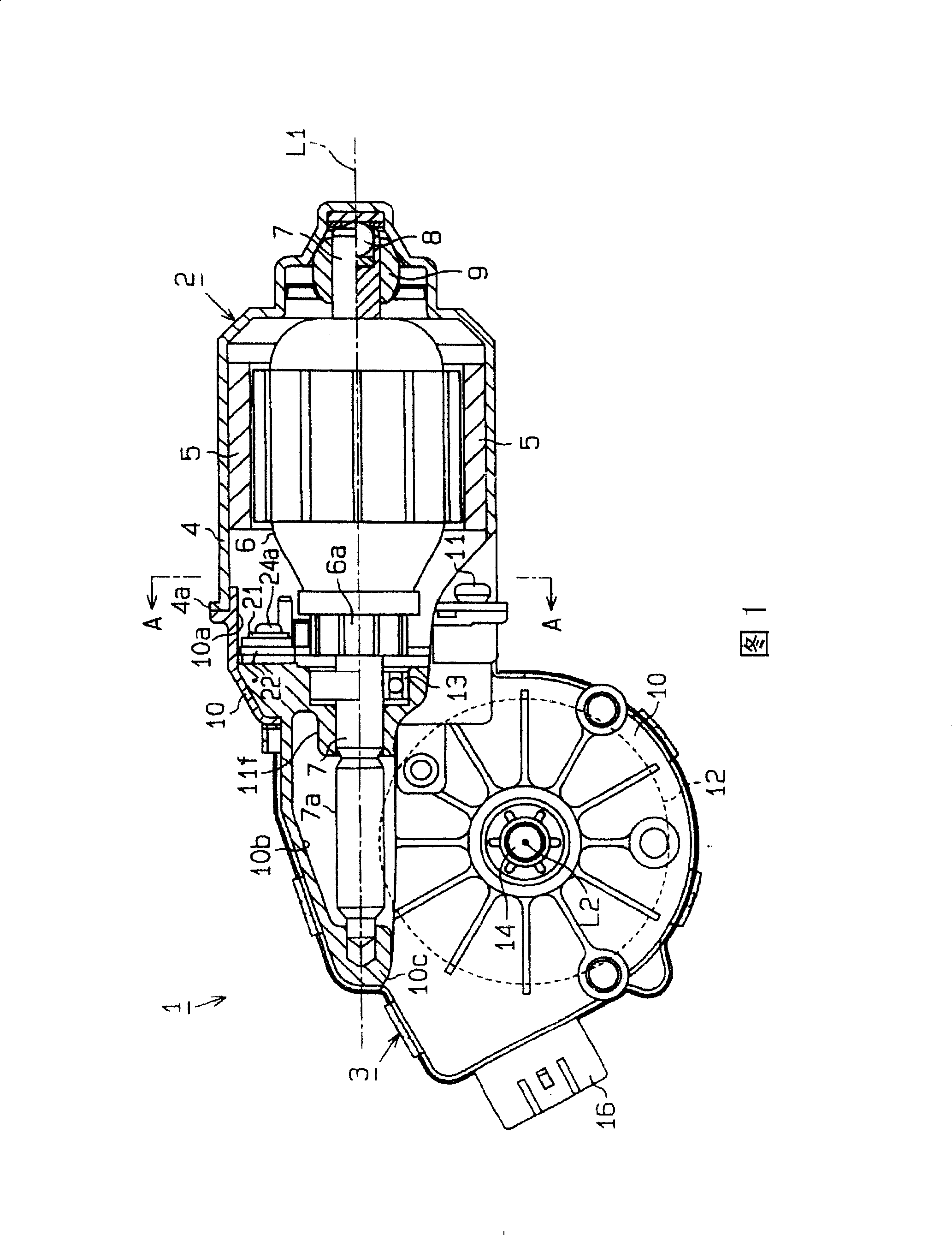
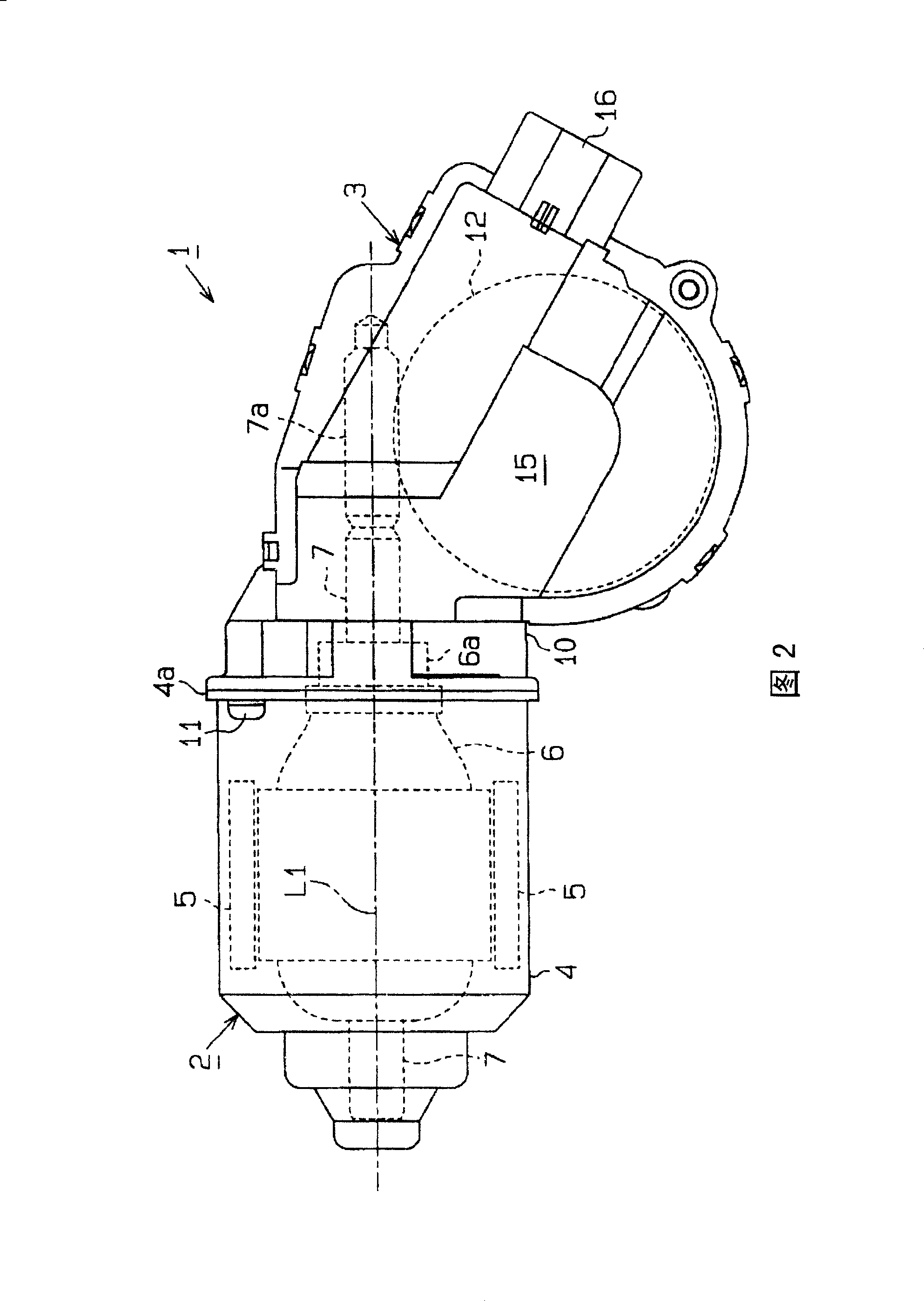
[0027] The wiper motor 1 shown in FIGS. 1 and 2 is used as a drive source of a vehicle wiper device for wiping off raindrops and the like adhering to a windshield (windshield) of a vehicle. This wiper motor 1 is composed of a motor main body 2 and a speed reduction unit 3 .

[0028] The yoke case 4 constituting the motor main body 2 is made of a conductive metal material and has a substantially cylindrical shape with a bottom. A plurality of magnets 5 are fixed to the inner peripheral surface of the yoke case 4 , and an armature 6 is rotatably accommodated inside each magnet 5 . At the bottom of the yoke case 4, a thrust bearing 8 and a radial bearing 9 that rotatably support the base end portion of the rotating shaft 7 of the armature 6 are provided. The gear case 10 of the deceleration unit 3 covering the head end side of the rotating shaft 7 forming the wo...


PUM


Abstract

A gear housing 10 has a support rib 10k formed thereon. When the female connection terminal portion 33a on the brush holder device 21 side and the male connection terminal portion 36a on the plate cover side are intruded and connected together, the support rib is engaged with a terminal supporting portion 35c that supports the female connection terminal portion 33a and holds a posture of the female connection terminal portion 33a, and thus holding the posture of the brush holder device 21. To provide a motor wherein, even if an intrusion connection force is exerted on a connection terminal portion formed in a brush holder device, a posture of the brush holder device is prevented from being changed and the state of contact between brushes held by the brush holder and a commutator is prevented from being changed.

Description

technical field [0001] The present invention relates to a motor having a structure in which connection terminal portions of two members are connected to each other when the members are assembled. Background technique [0002] Generally, a wiper motor mounted on a vehicle is a motor equipped with a speed reduction mechanism, that is, a motor body and a speed reduction unit that decelerates and outputs the rotation of the motor body are integrally assembled. That is, the motor main body rotatably accommodates an armature having a rotating shaft and a commutator in a bottomed cylindrical yoke housing, and the rotating shaft protrudes into the speed reduction unit. The deceleration unit accommodates a deceleration mechanism that decelerates the rotation of the rotating shaft and transmits it to the output shaft in a housing recess in the gear case, and a flat cover that closes the housing recess is attached to an opening of the housing recess. [0003] A brush holder holding a ...

Claims


Application Information

Patent Timeline
Patent Type & Authority Patents(China)
IPC IPC(8): H02K5/22H02K5/14H02K7/116H02K13/00H02K23/00
Inventor 大城昭郎
Owner DENSO CORP
Why Eureka
Try Eureka