CDMA mobile communication method, system and mobile station equipment
A mobile communication and mobile station technology, applied in the field of reception level control and handover operation, can solve the problems of communication interruption, a large number of control processing, etc., and achieve the effect of preventing instantaneous interruption
- Summary
- Abstract
- Description
- Claims
- Application Information
AI Technical Summary
Problems solved by technology
Method used
Image
Examples
Embodiment 1
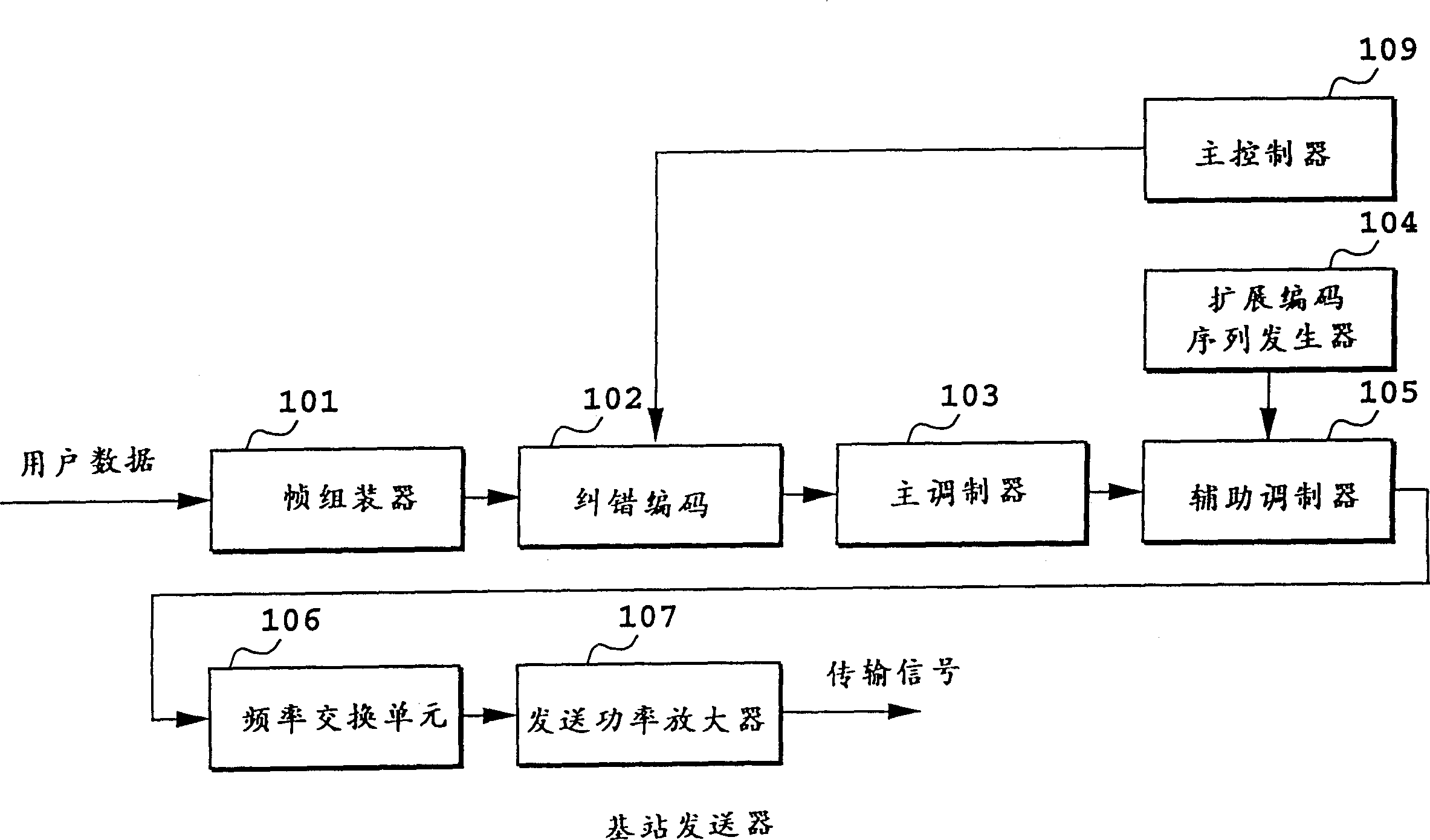
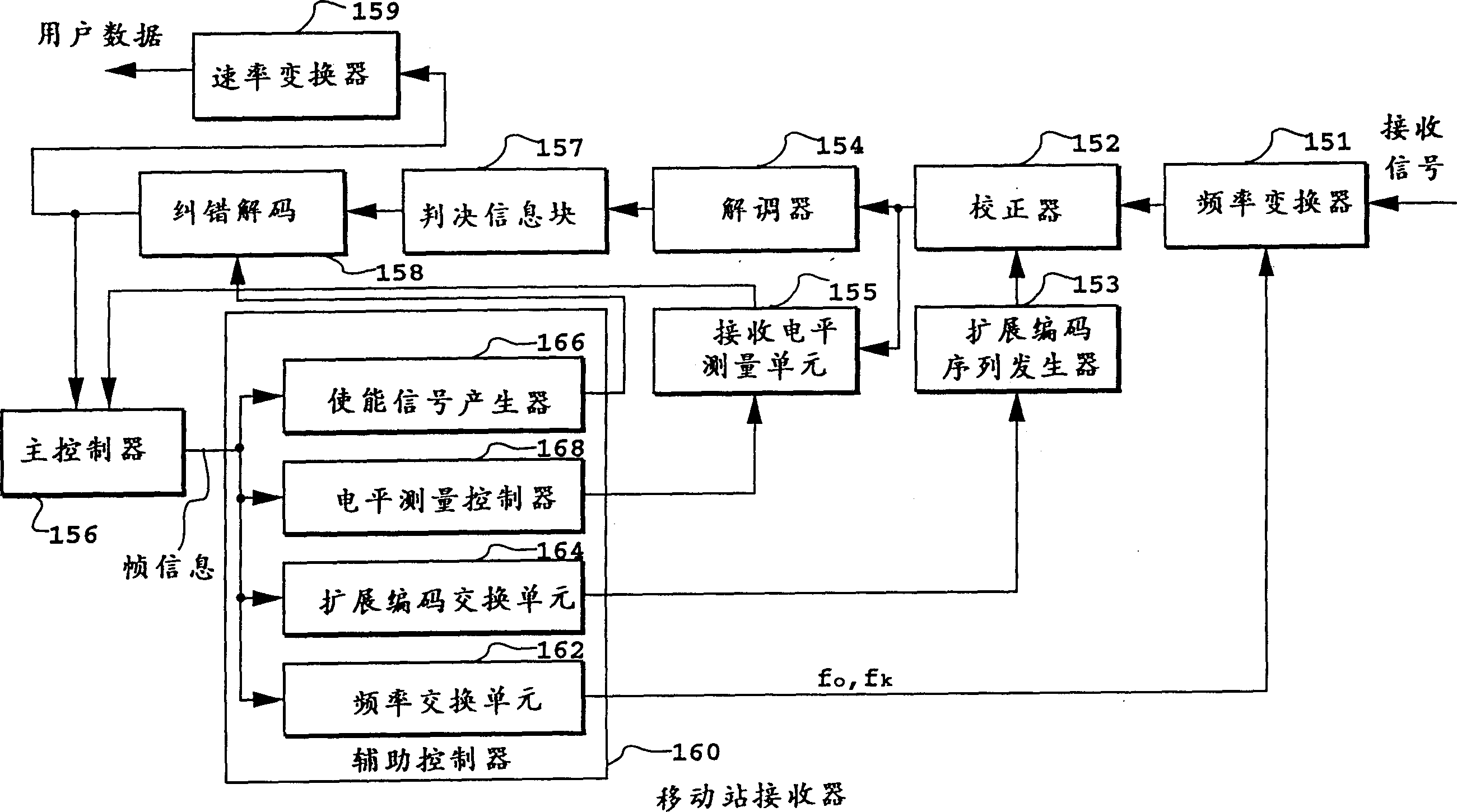
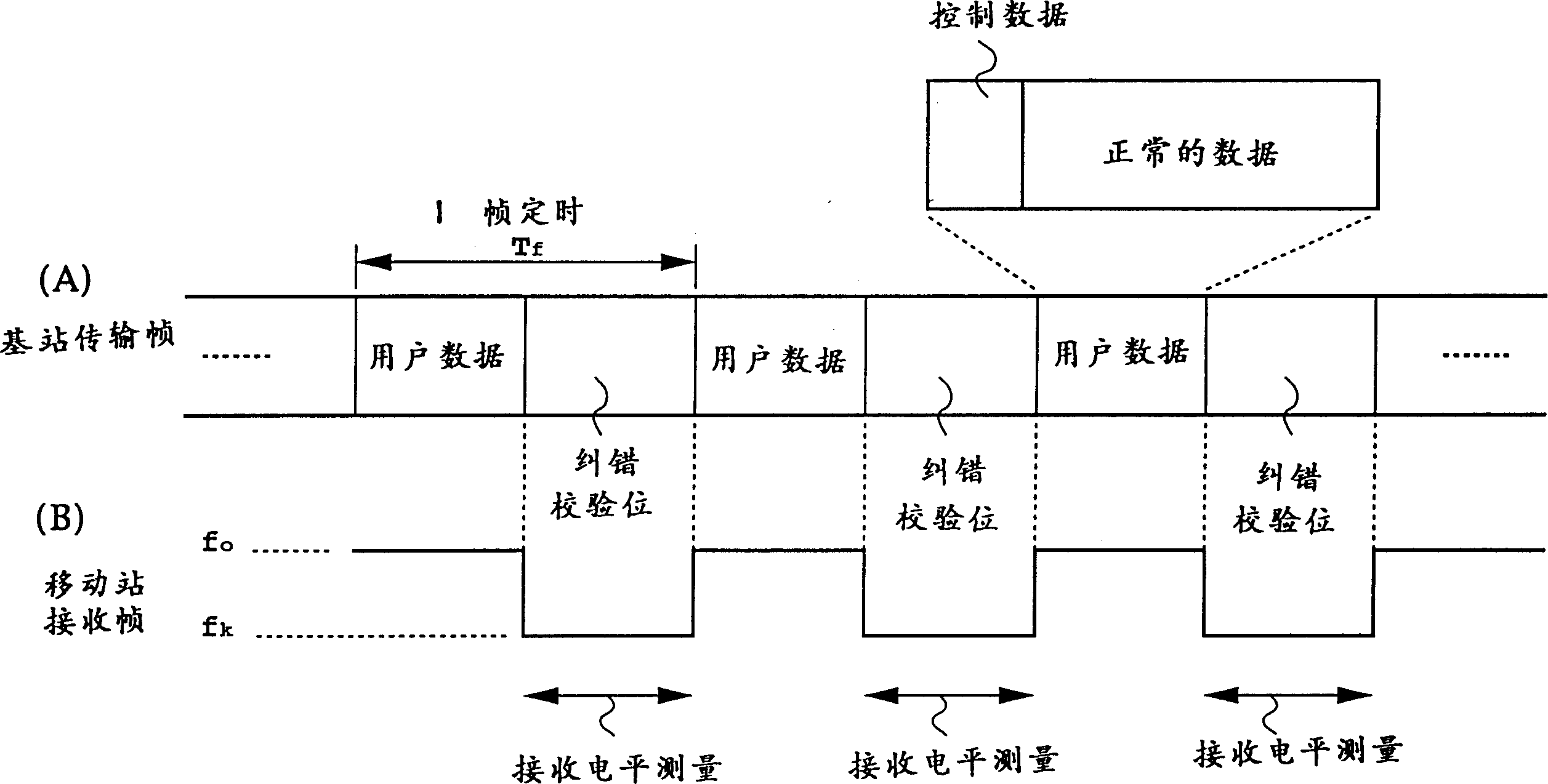
[0029] Figure 1A and 1B Represented is a block diagram of a first embodiment of a transmitter of a base station and a receiver of a mobile station of a CDMA mobile communication system according to the present invention, figure 2 Indicates the frame structure and receiving timing used in the present invention;
[0030] refer to Figure 1A , reference numeral 101 indicates a frame assembler for frame input data, 102 is an error correction encoder for error correction encoding of framed data, and 103 is a main frame for phase modulating the output of error correction encoder 102 Modulator. Numeral 105 denotes a secondary modulator for spreading the main modulated signal by the spreading code generated by the spreading code sequence 104 . 106 is a frequency converter for converting the spread signal into the transmission frequency. 107 is a transmission power amplifier for power amplification. 109 is a main controller for controlling the above-mentioned individual units.
...
Embodiment 2
[0039] Figure 3 shows another embodiment of the present invention. Figure 3A and 3B show a block diagram of a second embodiment of the construction of the CDMA mobile communication system according to the present invention. Figure 3A 3B shows the structure of the base station transmitter, and FIG. 3B shows the structure of the mobile station receiver. Figure 4 Shown is the frame structure and reception timing used in the present invention.
[0040] Figure 3A The transmitter of the base station is shown with Figure 1A Shown is the difference between the base station's transmitter and the Figure 3A There is a modulation level controller 304 in which, eg from quadrature phase modulation to hexadecimal phase modulation, controls the main modulation unit 303 to enable variable modulation levels.
[0041] Additionally, the mobile station receiver of Figure 3B is compatible with Figure 1B The difference between the base station receivers shown is that Figure 3B has a demod...
Embodiment 3
[0046] as in Figure 1A and 1B , figure 2 In the case of level monitoring described in the reference Figure 5 to Figure 8 Handover for changing base stations during communication using the same equipment will be described below.
[0047] The system architecture for handover is as Figure 5 shown. Mobile station 504 is in communication with communication base station 502 . As the measurement result, the new base station 503 is the best in the measurement results, and a handover to the new base station 503 is required. In this case, handover is under the control of the upper station 501 of the communication base station 502 and the new base station 503 .
[0048] FIG. 6 is a structural block diagram of the sending unit of the mobile station 504 . In this figure, the symbol 60X (X=1-7.9) corresponds to Figure 1A The symbol 10X in.
[0049] This sending unit is compatible with the Figure 1A The difference between the base station transmission units shown in is that the ...
PUM
 Abstract
Description
Claims
Application Information
 - R&D
- Intellectual Property
- Life Sciences
- Materials
- Tech Scout
- Unparalleled Data Quality
- Higher Quality Content
- 60% Fewer Hallucinations
Browse by: Latest US Patents, China's latest patents, Technical Efficacy Thesaurus, Application Domain, Technology Topic, Popular Technical Reports.
© 2025 PatSnap. All rights reserved.Legal|Privacy policy|Modern Slavery Act Transparency Statement|Sitemap|About US| Contact US: help@patsnap.com


