Scaled impedance replica for echo attenuation in digital transmission systems

A digital transmission and transmitter technology, applied in transmission systems, wired transmission systems, electrical components, etc., can solve the problem of increasing the number of pins

Inactive Publication Date: 2004-11-03
INFINEON TECH AG +1
View PDF1 Cites 0 Cited by
  • Summary
  • Abstract
  • Description
  • Claims
  • Application Information

AI Technical Summary

Problems solved by technology

In addition to the necessary external passive components attached to the chip, the increased pin count is a major drawback

Method used


Image

  • Scaled impedance replica for echo attenuation in digital transmission systems
  • Scaled impedance replica for echo attenuation in digital transmission systems

Examples


Embodiment Construction

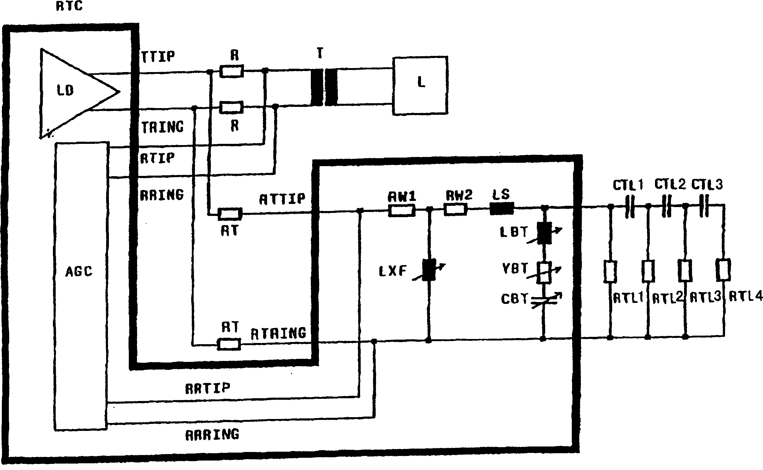
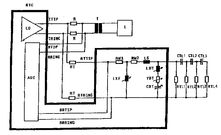
[0017] The receiver / transmitter chip (surrounded by thick lines) includes the line driver LD for driving the connector and ring signal lines TTIP and TRING. The signal received from the loop by the receiver / transmitter chip RTC is connected to the chip via the signal lines RTIP and RRING connected to the termination resistor R, the connector in front of R and the ring lines TTIP, TRING. The received signal is sent to a part AGC of the chip TRC which acts as a subtractor.

[0018] Since the received far-end signal is superimposed by the echo signal generated by signal propagation through the line driver LD, the echo signal must be removed. This is accomplished by generating artificial or replica echo signals and subtracting them from the sum of the received far-end signal and the echo signal. Impedance replicas include a replica transmit tap line RTTIP and a replica transmit loop line RTRING, connected to a transformer replica, a bridge tap replica and a signal loop replica (c...


PUM


Abstract

A device for echo attenuation in a digital transmission system comprises an impedance replica of the transmission path, wherein the impedance replica consists of a terminating resistor replica, a transformer replica and a transmission line replica. Further the device can comprise an additional bridged tap replica. The transformer replica and the bridged tap replica are located on chip and the main transformer inductance replica and all components of the bridged tap replica are made variable so that a software setting is possible.

Description

technical field [0001] The present invention relates to a device for echo cancellation as known from EP 0 693 846 A2. Background technique [0002] In a semiconductor-based digital transmission system, such as ISDN or XDSL, transmit and receive signals are carried from location A to B on the same pair of metal wires. Unless special precautions are taken, the received signal (referred to below as the far-end signal) is overlaid by the own transmitter's signal, referred to as echo. This has two disadvantages: [0003] a) Receive path inputs must be designed for high input levels. Thus, the possible signal-to-noise ratio (S / N) is limited. [0004] b) In usual ISDN and XDSL transmission systems you find digital linear echo compensators after the analog receive path. Such echo compensators are not capable of subtracting nonlinear distortion components from the echo. The signal-to-distortion ratio (S / D) must therefore be kept very low. [0005] In order to overcome the above...

Claims


Application Information

Patent Timeline
Patent Type & Authority Patents(China)
IPC IPC(8): H04B3/20H04B3/23H04Q1/56
CPCH04B3/23
Inventor T·布隆M·格雷尔M·莫亚尔D·M·乔菲
Owner INFINEON TECH AG
Why Eureka
Try Eureka