
Clutch device with lock

A technology of clutch device and lock, which is applied in the direction of door/window protection device, window/door, building components, etc. It can solve the problems of complex structure, time-consuming and labor-intensive operation, and large expenditure of force, and achieve the effect of long opening arm

Inactive Publication Date: 2005-02-23
史建刚
View PDF0 Cites 0 Cited by
  • Summary
  • Abstract
  • Description
  • Claims
  • Application Information

AI Technical Summary

Problems solved by technology

The principle of leverage is not used, even if the principle of leverage is adopted, because the moment arm is too short, relatively speaking, it takes a lot of force, and the structure is complicated, and the operation is time-consuming and laborious

Method used


Image

  • Clutch device with lock
  • Clutch device with lock
  • Clutch device with lock

Examples


Embodiment Construction

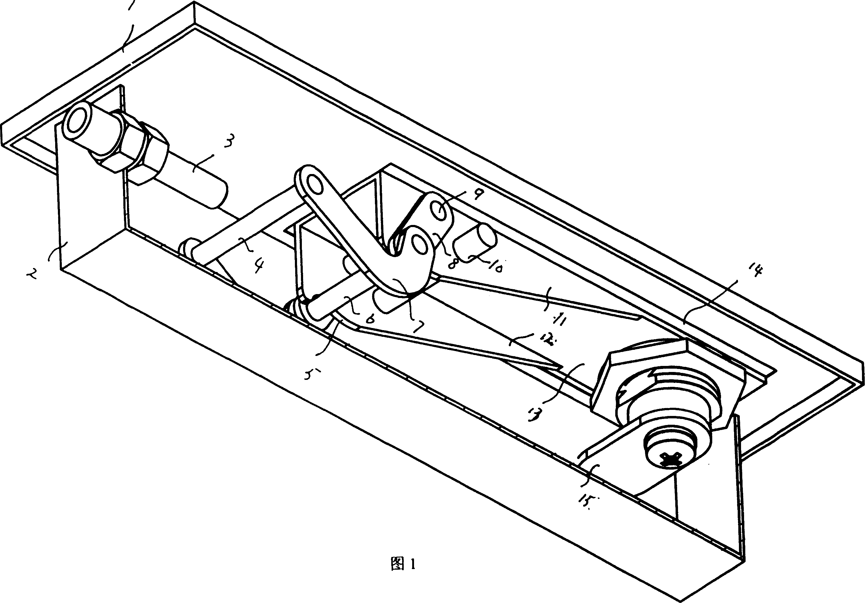
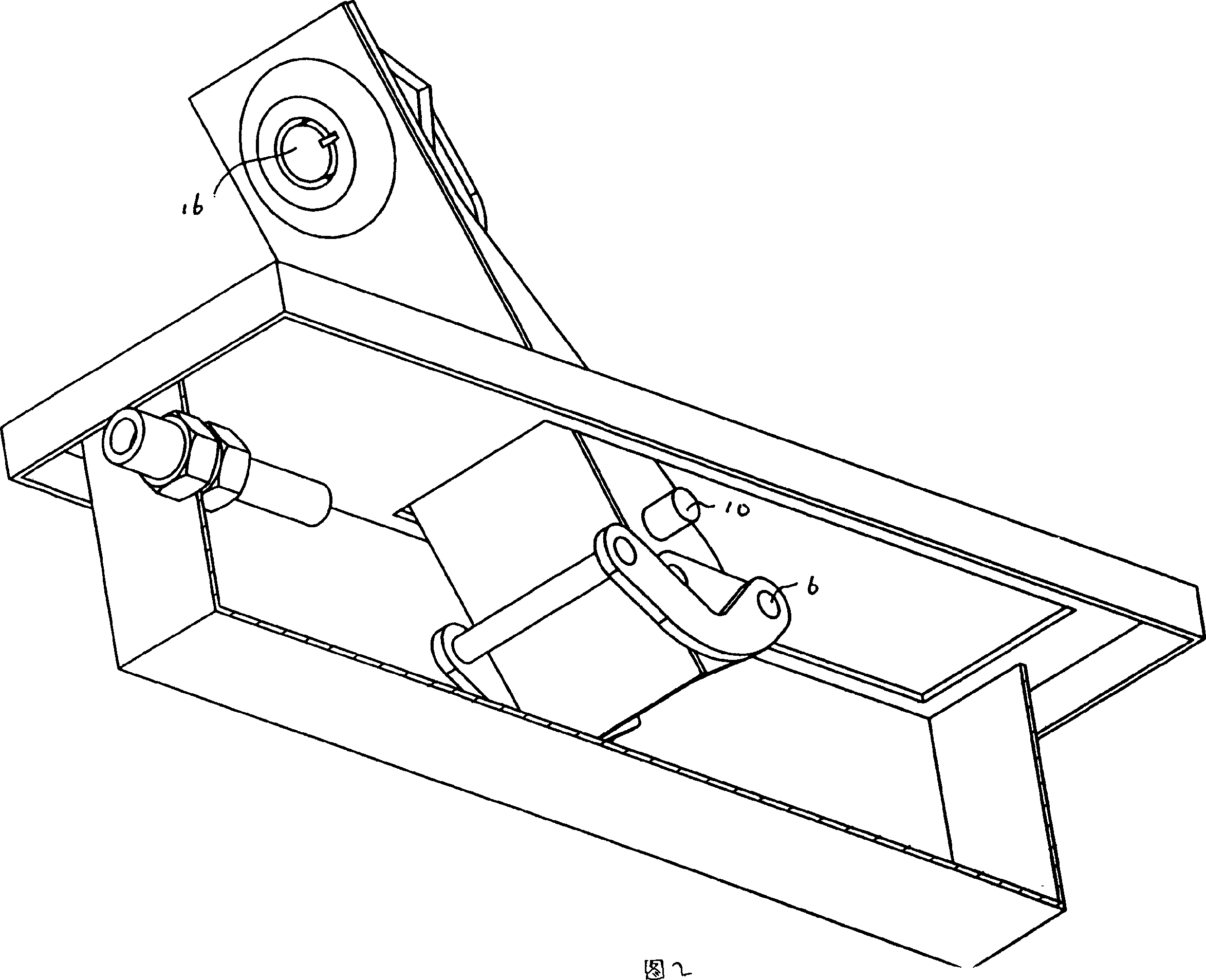
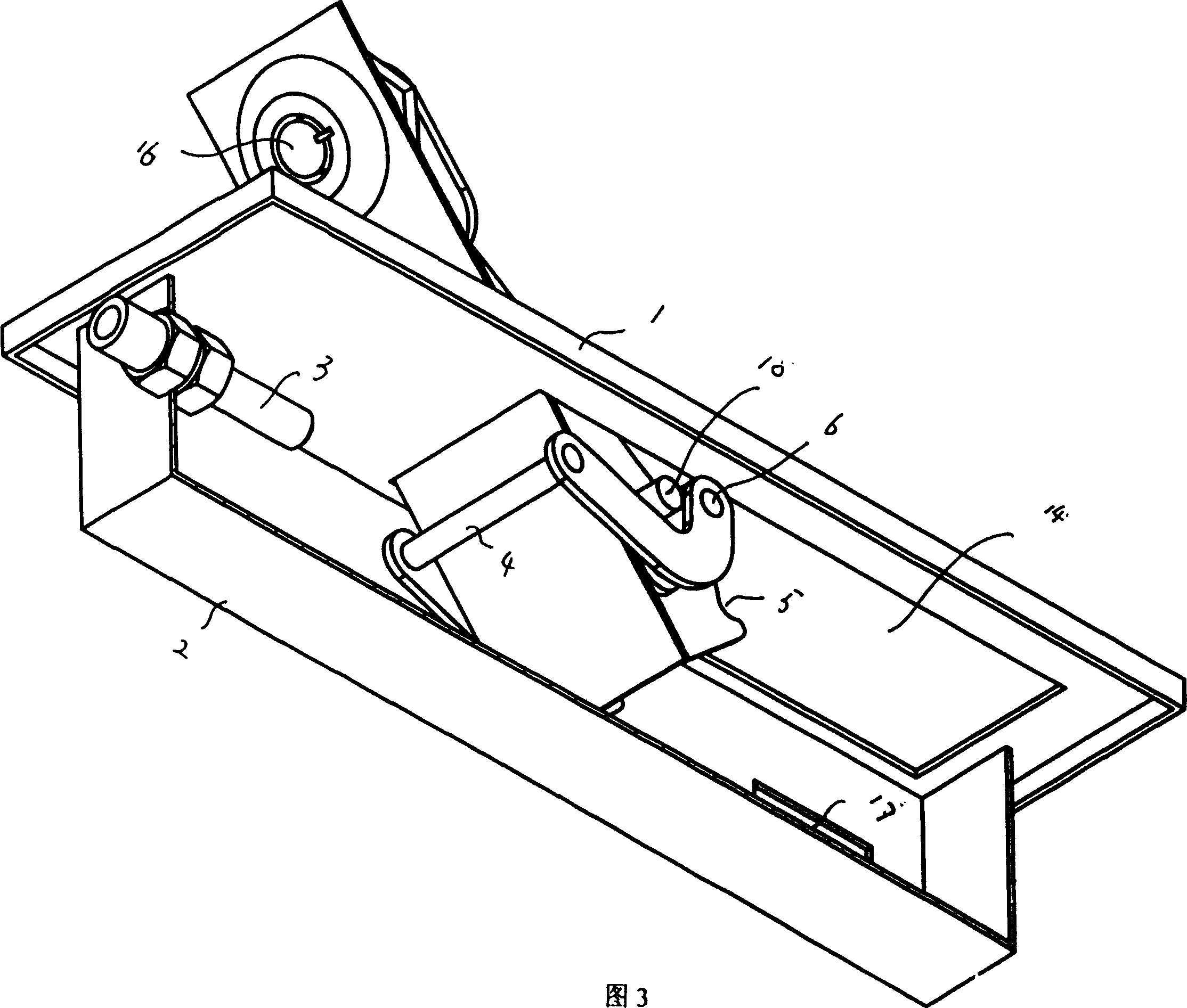
[0009] As shown in Figures 1 to 3, the present invention is a clutch device with lock. It is mainly composed of a lock cover 1, a lock seat 2, a lock mechanism and a traction tube 3, etc. The lock mechanism is placed in the seat 2 under the lock, and the cover 1 cover is placed on the seat 2 under the lock, and the traction tube 3 is put on the seat 2 front side plate under the lock, and is fixed with the front side plate with two nuts.

[0010] The lock mechanism is mainly composed of top plate 13, side plates 11, 12, two waist-shaped rear connecting rods 8, two L-shaped front connecting rods 7, front connecting rod 4, middle lock shaft 6, rear pin shaft 9, total pin Axle 10, lock core 16 and waist shape dead bolt 15 form. The top plate 13 is rectangular in appearance, and the two side plates 11, 12 are left and right downwards connected to the two sides of the front portion of the top plate 13, and an arc-shaped groove 5 is provided at the front lower part of the two side p...


PUM


Abstract

The present invention relates to a clutch device with lock. It includes lock upper cover, lock lower seat and locking mechanism, said locking mechanism is placed in the lock lower seat, and the locking mechanism includes top plate, two side plates, two rear-connecting bars, two front connecting bars, middle pin shaft, lock barrel and striking plate. After the clutch is opened, it can effectively self-locked.

Description

Technical field: [0001] The present invention relates to a clutch device with lock. Installed on various motor-controlled garage doors or shutter doors. Background technique: [0002] The most advanced clutch device on the market is nothing more than a stay cord with a clutch left. When the door is to be opened manually, the stay cord connected to the clutch is first pulled down by hand. If the principle of leverage is not adopted, even if the principle of leverage is adopted, because the moment arm is too short, relatively speaking, the force expended is also large, and the structure is complicated, and the operation is time-consuming and laborious. Invention content: [0003] The object of the present invention is to overcome the above disadvantages and provide a labor-saving clutch device with lock. [0004] The purpose of the present invention is achieved in this way: a clutch device with lock, which includes a lock cover, a lock seat, a lock mechanism and a traction...

Claims


Application Information

Patent Timeline
Patent Type & Authority Patents(China)
IPC IPC(8): E06B9/56
Inventor 史建刚
Owner 史建刚
Learn More