
A kind of infusion pump with rotation lock, rotation lock and method

A technology of rotary lock and infusion pump, which is applied to pressure infusion, drug devices, and devices introduced into the body. Effect

Active Publication Date: 2018-05-01
苏州麦德迅医疗科技有限公司
View PDF7 Cites 0 Cited by
  • Summary
  • Abstract
  • Description
  • Claims
  • Application Information

AI Technical Summary

Problems solved by technology

[0003] The object of the present invention is: to provide an infusion pump with a rotary lock, a rotary lock and a method thereof, which firstly solves the hidden danger of the medicine box being loosened and the infusion pump unable to work normally due to the misoperation of non-medical personnel to unlock, and secondly, through structural optimization, reduce Reduce the manufacturing and maintenance costs of the previous locks with complex mechanisms, and improve the economy of the product

Method used


Image

  • A kind of infusion pump with rotation lock, rotation lock and method
  • A kind of infusion pump with rotation lock, rotation lock and method
  • A kind of infusion pump with rotation lock, rotation lock and method

Examples


Embodiment

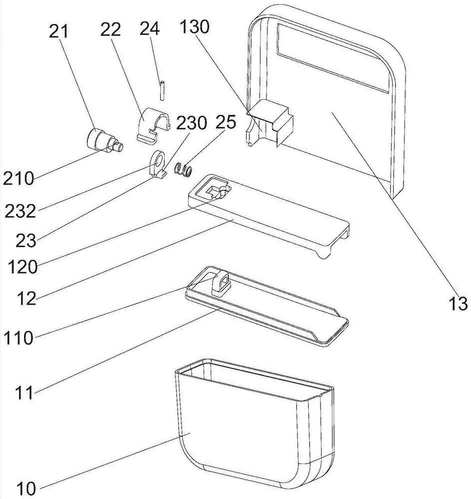
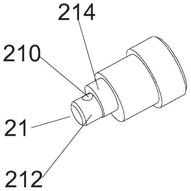
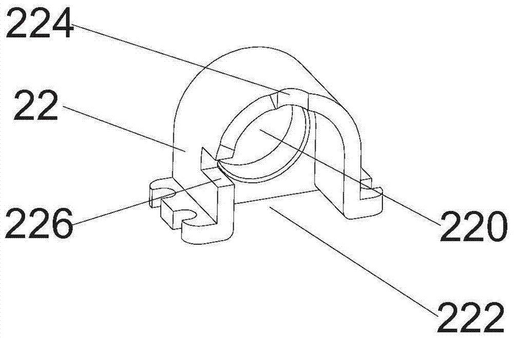
[0029] Example: such as Figure 1-7 As shown, the present invention provides a first embodiment of an infusion pump with a rotary lock, which includes: a medicine box 10 for accommodating a medicine solution bag, a cover fixedly connected to the upper end of the medicine box 10 and protrudingly provided with a locking portion 110 The plate 11, the frame 12 that is arranged above the cover plate 11 and allows the locking part 110 to pass through, the front and rear half shells 13 that are fixedly arranged on both sides of the frame 12 and are interlocked with each other, are accommodated by the front and rear half shells 13 and can The rotating shaft 21 that locks and cooperates with the locking part 110, the fixing frame 22 that allows the rotating shaft 21 to partially pass through, the locking hook 23 that is accommodated by the fixing frame 22 and can be pushed by the rotating shaft 21, and the rotating shaft 21 that drives the rotation The key, the fixed pin 24 that can st...

no. 3 example

[0036] At the same time, on the basis of the above structure, the present invention provides a third embodiment of a method, which includes:

[0037]S1: First, the medicine box and the cover plate are connected by ultrasonic welding to form a medicine box assembly, and at the same time, the frame is fixedly connected with the pump head assembly;

[0038] S2: Then assemble the pump head assembly and the medicine box assembly together, wherein the locking part passes through the frame;

[0039] S3: Then put the rotating shaft, fixing frame, locking hook and elastic parts into the positioning grooves of the front and rear half shells, wherein the rotating shaft is fixed with a fixed pin, and the fixing frame is provided with first and second grooves corresponding to different states ;

[0040] S4: Fix the front and rear half-shells to the frame;

[0041] S5: When locking, push the rotating shaft to move axially, compress the elastic part to shrink, and the fixing pin comes out ...


PUM


Abstract

The invention discloses an infusion pump with a rotation lock, the rotation lock and a method; the infusion pump comprises a medicine box, a cover plate fixed on the top of the medicine box and provided with a protruding locking portion, a machine rack arranged above the cover plate and allowing the locking portion to pass, front and back half housings fixed on two sides of the machine rack and mutually buckled, a rotatable rotation shaft with at least a part contained by the front and back half housings, a fixed rack allowing partial the rotation shaft to pass and used for fixing the rotation shaft at least on two positions, a locking piece contained by the fixing rack and pushed by the rotation shaft so as to match and buckle with the locking portion, a fixing pin matched with the rotation shaft and used for fixing the rotation shaft at least on two positions, and an elastic piece enabling the locking piece to make reverse direction motions and sleeved on one end of the rotation shaft. The infusion pump can be effectively self-locked so as to ensure a medicine box assembly not to be dropped in usage, thus solving safety problems caused by mal-operation unlocking, reducing making and maintenance cost of a lock in a conventional complex mechanism, and improving product economic property.

Description

technical field [0001] The invention relates to an infusion pump with a rotary lock, a rotary lock and a method. Background technique [0002] As a common clinical treatment method, infusion pump medicine is used to inject medicine or medicine into the patient's body, and has been widely used in various fields of medical practice. However, the existing portable infusion pump medicine box fixed lock has two forms: 1. manual locking or unlocking structure; 2. locking or unlocking medicine box structure by a key. The manually operated structure may fall off during use or be unlocked by non-medical personnel by misoperation, resulting in the loosening of the medicine box, affecting the normal delivery of the medicine solution, and even causing serious injury or death to the patient. The other kind of indenting or unlocking the medicine box by a key has a complex mechanism, takes up a lot of space, has high manufacturing and maintenance costs, and does not have good economy. C...

Claims


Application Information

Patent Timeline
Patent Type & Authority Patents(China)
IPC IPC(8): A61M5/142
CPCA61M5/142A61M2205/276
Inventor 寇唐奎于鑫淼
Owner 苏州麦德迅医疗科技有限公司
Learn More