Tank flange

一种燃料容器、法兰的技术,应用在燃料容器法兰领域,达到节省结构空间的效果

Inactive Publication Date: 2009-12-16
ROBERT BOSCH GMBH +1
View PDF1 Cites 6 Cited by
  • Summary
  • Abstract
  • Description
  • Claims
  • Application Information

AI Technical Summary

Problems solved by technology

The disadvantage is that in order to change the filter fabric, a large area of ​​the filter cover has to be opened

Method used


Image

  • Tank flange

Examples


Embodiment Construction

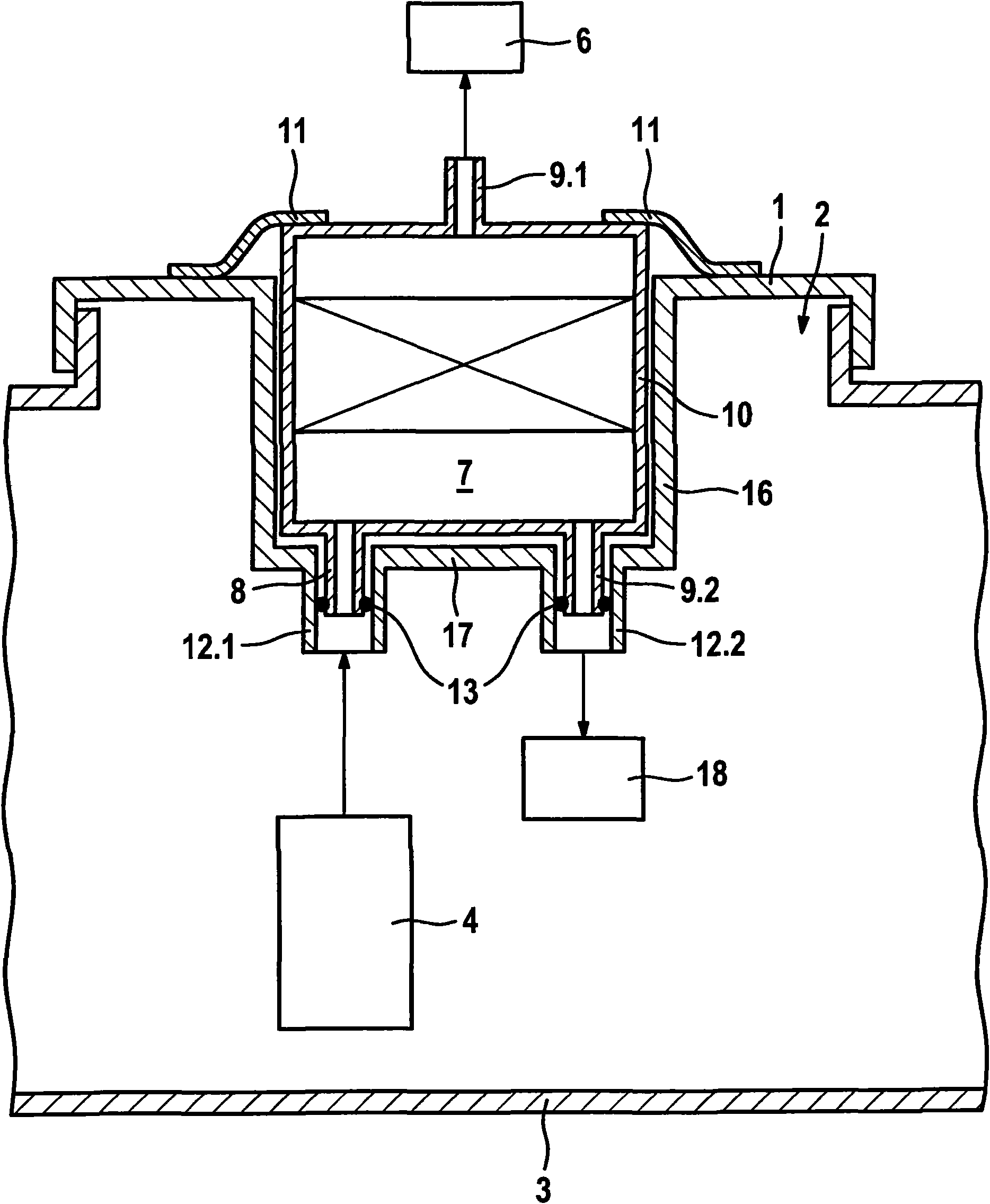
[0011] The drawing shows a fuel container flange according to the invention.

[0012] The fuel container flange 1 according to the invention is designed as a cover closing the fuel container opening 2 of a fuel container 3 . The fuel container opening 2 is necessary in order to allow a device for delivering fuel, for example a so-called fuel delivery module, to be inserted into the fuel container 3 . The device for delivering fuel comprises at least one delivery device 4 , for example an electric fuel pump. After these components have been installed in the fuel container 3 , the fuel container opening 2 is hermetically closed by the fuel container flange 1 . Delivery device 4 delivers fuel from fuel container 3 to internal combustion engine 6 . Between the delivery device 4 and the internal combustion engine 6 there is a main filter 7 which filters out fine dirt particles from the fuel. The main filter 7 has an inlet 8 and at least one first outlet 9 . 1 and is arranged on ...


PUM


Abstract

Known tank flanges have a main filter which has a filter housing with an inlet and an outlet, and a first connecting duct for connecting the main filter to a feed unit. The filter housing is integrated in the tank flange, wherein the filter fabric is inserted into the filter housing and the filter housing is closed off by means of a filter cover. The inlet of the filter housing is connected to the pressure side of a feed unit and the outlet leads to an internal combustion engine. A disadvantage is that, in order to exchange the filter fabric, the large-area filter cover must be opened, as a result of which a large amount of fuel vapour is dissipated to the atmosphere. In the case of the tank flange according to the invention, the exchangeability of the main filter is simplified by virtue of the main filter being embodied as a filter cartridge. It is provided according to the invention that the inlet (8) of the main filter (7) extends into the first connecting duct (12) of the tank flange (1) and forms a sealed connection.

Description

technical field [0001] The invention relates to a fuel container flange of the type claimed in the independent claim. Background technique [0002] A fuel container flange is already known from EP 0 612 919 A1, which comprises a main filter and a first connecting channel for connecting the main filter to a delivery device, the main filter having an inlet and an outlet part of the filter housing. The filter housing is integrated in the fuel tank flange, the filter fabric being mounted in the filter housing and the filter housing being closed by a filter cover. The inlet of the filter housing is connected to the pressure side of the delivery device and its outlet leads to the internal combustion engine. This has the disadvantage that in order to replace the filter fabric, a large-area filter cover must be opened. Contents of the invention [0003] In contrast, the fuel container flange according to the invention with the features of the characterizing part of the independ...

Claims


Application Information

Patent Timeline
Patent Type & Authority Applications(China)
IPC IPC(8): F02M37/22B01D35/027
CPCF02M37/10B01D35/027F02M37/22F02M37/0076F02M37/50F02M37/42
Inventor B·奥斯瓦尔德A·米勒K·格贝特P·舍尔哈斯
Owner ROBERT BOSCH GMBH
Why Eureka
Try Eureka