Crimped casing for electric transmission and distribution wire

A technology for crimping sleeves and power transmission and distribution lines, which is applied in the direction of connection where permanent deformation works, and can solve problems such as disconnection, power line blackout accidents, and corrosion.

Inactive Publication Date: 2003-04-09
陈国雄
View PDF0 Cites 6 Cited by
  • Summary
  • Abstract
  • Description
  • Claims
  • Application Information

AI Technical Summary

Problems solved by technology

[0055] 10. The existing US-standard C-shaped aluminum crimping clamp, in order to improve the tensile capacity of the clamp, is realized by lengthening the length of the clamp, so the number of crimping increases, and the problem caused by this is that the crimped wire The clip body is in a curved shape. During the "live work" of the power line, its "open and closed safety insulating rubber tube" cannot penetrate the covering. If it is forced to penetrate, the curved live part will be exposed outside the tube, forming "live work" Difficulties and potential job safety crisis of electric shock accidents for live workers
[0056] 11. Existing C-shaped aluminum crimping clamps, after crimping, the clamp entity presents a curved shape. When the bending angle is large, due to the temperature difference between day and night and the peak off-peak load, thermal expansion and contraction are caused. Breakage at the bend causes loosening or disconnection of connecting wires, resulting in power line outages, increasing power loss and reducing power supply revenue
[0057] 12. Existing C-shaped copper and aluminum crimping clamps. After the crimping of the clamps, the wire groove and the wires are flat. The resulting wires are loose, corroded, and disconnected, resulting in power line failures, which will lead to "out-of-phase operation" , burning the user's equipment, causing losses to the user or the power company, and causing a compensation dispute between the user and the power company

Method used


Image

  • Crimped casing for electric transmission and distribution wire
  • Crimped casing for electric transmission and distribution wire
  • Crimped casing for electric transmission and distribution wire

Examples


Embodiment 2

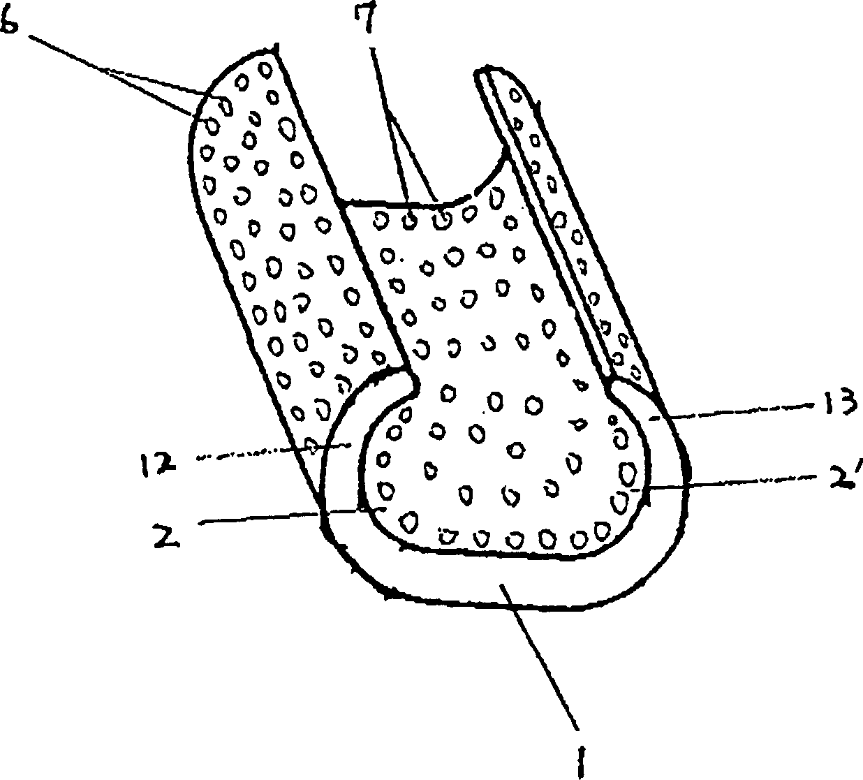
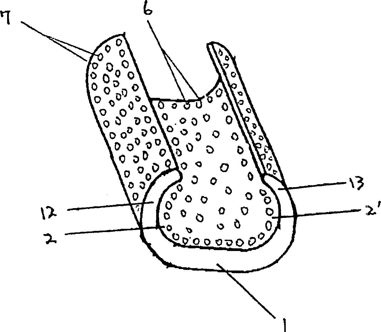
[0111] Embodiment two, such as figure 2 As shown, the difference between this embodiment and the previous embodiment is that the locking protrusion 7 is provided on the outer surface of the base 1 , and the locking recess 6 is provided on the inner surface of the base 1 . At the beginning of crimping, the recesses on the inner surface will be closed early, which is beneficial to improve the compressive stress on the inner surface of the cable clamp and help the bending of the hook part of the cable clamp; the locking protrusion on the outer surface improves the strength and helps the clamp The tail end of the hook fits the wire, which is conducive to crimping and close contact with the wire, so that the wire clip can effectively cover the wire in the shape of a wire diameter, and the wire clip is approximately cylindrical. When the locking protrusions and locking recesses are distributed in a point shape, the recesses and protrusions have the same effect.

Embodiment 3

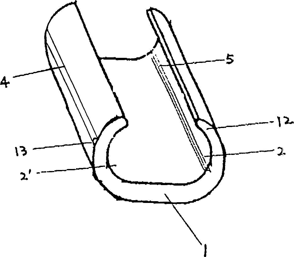
[0112] Embodiment three, such as Figure 3A , 3B , 3C, and 3D, a crimping sleeve for transmission and distribution lines of the present invention, the sleeve is composed of a columnar base 1 with a C-shaped cross section, and the two ends of the base 1 are two wires that are in contact with the wires. Grooves 2, 2', the two grooves 2, 2' are surrounded by hooks 12, 13 of upper and lower semicircular arcs of a C shape, and the grooves 2, 2' are in the shape of through holes; A locking rod 4 and a locking groove 5 are also provided on the surface of the base body.

[0113] like Figure 3A As shown, the shape of the locking rod 4 is a semi-cylindrical shape parallel to the length of the wire clamp; the shape of the locking groove 5 is a straight groove with a V-shaped cross section and parallel to the length direction of the wire clamp; the locking rod 4 is set At the apex of the outer surface of the hook portion 13 surrounding the line groove 2 ′, the locking groove 5 is prov...

Embodiment 4

[0118] Embodiment four, such as Figure 4A , 4B As shown, a crimping sleeve for transmission and distribution lines of the present invention is composed of a columnar base 1 with a C-shaped cross-section, and two wire grooves 2 and 2 in contact with the wires are formed at both ends of the base 1. ', the two grooves 2, 2' are surrounded by two C-shaped upper and lower half-arc hooks 12, 13, and the grooves 2, 2' at both ends are in the shape of through holes. Two locking rods 4 are also arranged on the surface of the clip base 1 .

[0119] like Figure 4A As shown, the locking rod 4 is arranged on the vertices of the outer surfaces of the two hooks 12, 13, and the locking rod 4 is composed of discontinuous locking protrusions 7 arranged in a straight line along the length direction of the clamp. , the shape of the locking protrusion 7 is a semi-cylindrical shape along the length direction of the wire clamp, and the locking bar 4 is a discontinuous linear semi-cylindrical sh...


PUM


Abstract

This invention discloses a crimp connection for casing tube or crimped lock for wire used in power transmission and distribution line composed of a columnary matrix, the section of which exhibits C shape, two lineal furrows are set at both ends point distributed locking reentrants/humps or continuous or discontinuous locking furrows or locking ribs are set up on the surfaces of inner/output surfaces of the matrix and the furrows to stitch the crimped lock with wires due to the above-mentioned crimped lock structure, increasing its pulling force, reducing its connection adapted resistance and temperature rising.

Description

technical field [0001] The present invention relates to a kind of electric power fittings, in more detail, it relates to a kind of crimping sleeve mainly used for high and low voltage transmission and distribution lines, which is a kind of copper, aluminum or other metal which can be crimped together with the wire. Material C-shaped crimp sleeve. Background technique [0002] The crimping sleeve is commonly known as "clamp", which is a commonly used electric power fitting. It is divided into two types: "tension type clamp" and "non-tension type clamp". " and pressure " crimping type " two kinds. [0003] At present, the "bolt locking type" "parallel groove clamp" is widely used in China. This kind of clamp is to process two grooves and two or more bolt holes on a thick aluminum plate, and then use two Or two or more bolts lock two double-groove aluminum sheets to complete the connection between the wire and the wire. The contact area between the wire clamp and the wire is ...

Claims


Application Information

Patent Timeline
Patent Type & Authority Applications(China)
IPC IPC(8): H01R4/18
Inventor 陈国雄
Owner 陈国雄
Why Eureka
Try Eureka