Ratary handle type connector

A connector and rotary handle technology, applied in the direction of connection, parts and electrical components of the connecting device, etc., can solve the problems of difficulty in separating the female connector and the male connector from each other, hindering the operation of the rotary handle, etc.

Inactive Publication Date: 2003-12-10
SUMITOMO WIRING SYST LTD
View PDF1 Cites 6 Cited by
  • Summary
  • Abstract
  • Description
  • Claims
  • Application Information

AI Technical Summary

Problems solved by technology

Because sand and dust are located between the cam pin and the surface of the cam groove, thus hindering the operation of the handle, this makes it difficult to separate the female and male connectors from each other

Method used


Image

  • Ratary handle type connector
  • Ratary handle type connector
  • Ratary handle type connector

Examples


Embodiment Construction

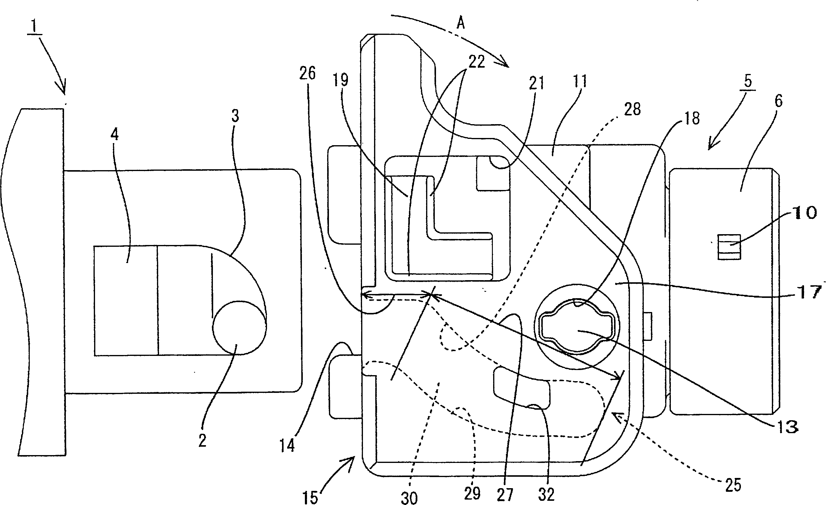
[0020] The following will refer to Figure 1 to Figure 7 An embodiment of the present invention is described. figure 1 A rotary handle connector with a male connector 1 and a female connector 5 is shown.

[0021] The male connector 1 accommodates a terminal male fitting (not shown). A boss 4 protrudes from each outer wall of the male connector 1 . A cam pin 2 protrudes from the upper surface of each boss 4 . The front edge of each boss 4 is made into a roughly arc shape, forming a loosening portion 3 .

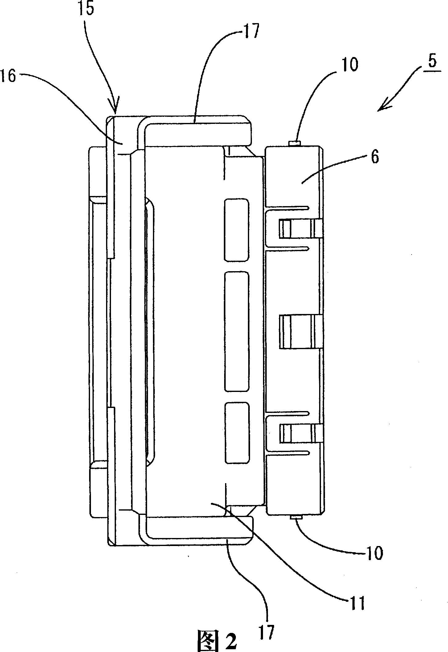
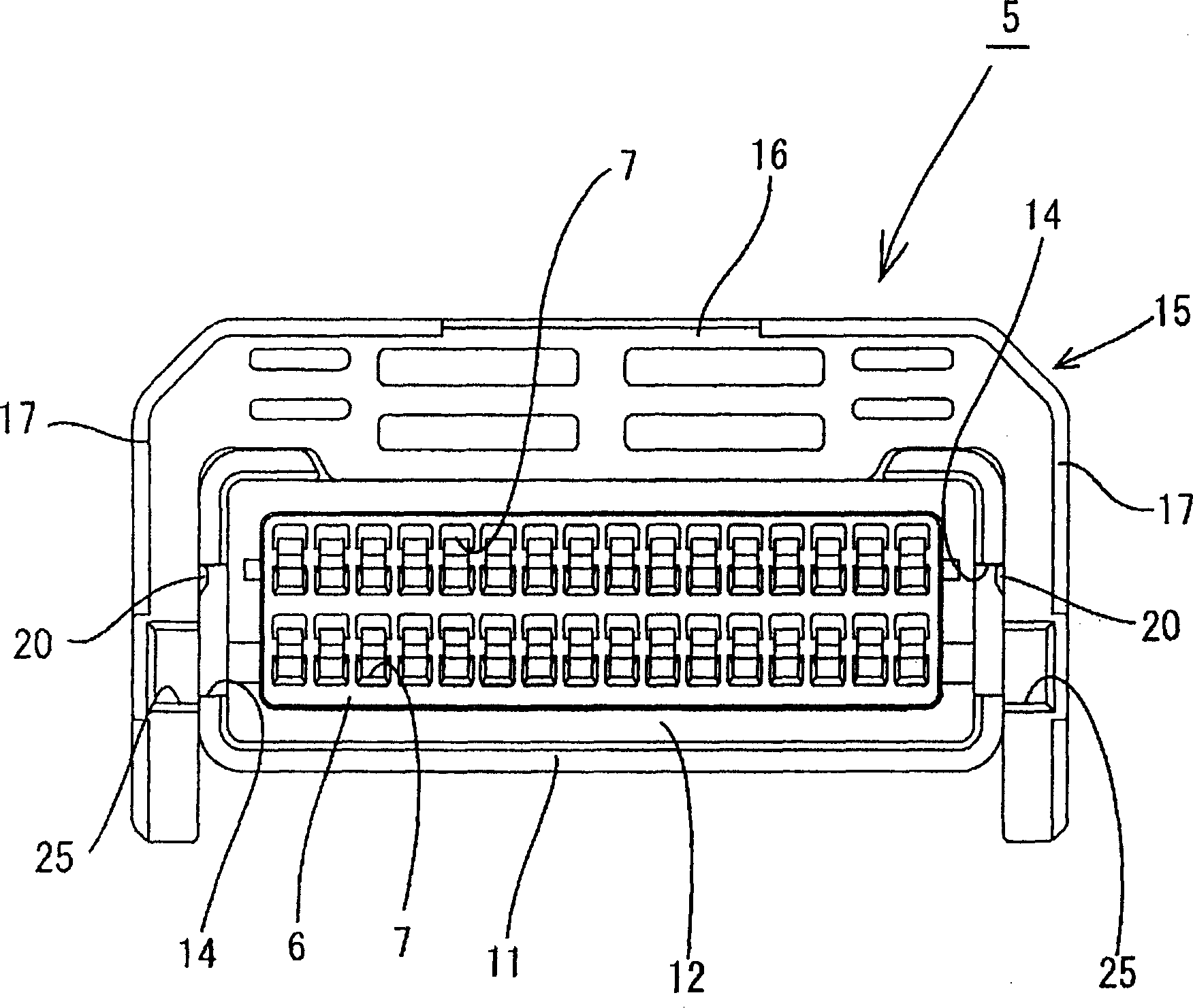
[0022] The female connector 5 has a main body 6 , a cover portion 11 located on the front side of the main body 6 , and a knob 15 rotatably mounted on the cover portion 11 .

[0023] Such as image 3 As shown, a plurality of slots 7 capable of accommodating terminal female joints (not shown) pass through the main body 6 in a front-to-back direction (ie, the mating direction of the connector). It can be inserted therein from the opening at the back of the slotted hole 7 ....


PUM


Abstract

A cam pin (2) is provided on a male connector (1). A cam groove (25) is formed on a lever (15) of a female connector (5). On a bottom surface (30) of a cam part (27) of the cam groove (25), an escape hole (32) is formed at the side of a cam surface (28) for separation, with the escape hole (32) penetrates through an outer wall of a cam plate part (17). The groove width of the cam part (27) is larger than the outer diameter of the cam pin (2). Even though foreign matter such as sand penetrates into the cam groove (25) in a fitted state of the female connector (5) and the male connector (1), the foreign matter can be discharged from the escape hole (32) to the outside of the connector. If some foreign matter does not pass through the escape hole (32) but is left in the cam part (27), the groove width of the cam part (27) is larger than the outer diameter of the cam pin (2) so that the foreign matter does not interfere with a movement of the cam pin (2).

Description

technical field [0001] The invention relates to a rotary handle connector. Background technique [0002] A conventional knob type connector disclosed in Japanese Patent Application Laid-Open No. 10-334986 is described below. The female connector has a turning handle which can be rotated along the pin shaft arranged on the side of the female connector. A cam groove on the inner surface of the knob receives a cam pin of the male connector. The knob turns with a cam pin that fits into the entrance of the cam groove. In this way, the cam pins are introduced into the inner bottom ends of the cam grooves, so that the joints are pulled toward each other and fitted together. [0003] The knob type connector having the above structure is installed on a two-wheeled vehicle or a handcart. When mounted on a cart, this connector can easily become clogged with sand or mud. If dust or the like enters the inner bottom end of the cam groove, there is no place to discharge the dust when ...

Claims


Application Information

Patent Timeline
Patent Type & Authority Applications(China)
IPC IPC(8): H01R13/52H01R13/629
CPCY10T403/595Y10T403/7071H01R13/62933H01R13/62905
Inventor 田中宣吉
Owner SUMITOMO WIRING SYST LTD
Why Eureka
Try Eureka