Electronic control for a hydraulically driven generator

a technology of electric control and hydraulic system, applied in the direction of electric generator control, dynamo-electric converter control, fluid coupling control, etc., can solve the problems of engine electrical power, engine speed variations wreak havoc, and difficulty in maintaining precise frequency output for controlling

Active Publication Date: 2012-09-18
UUSI
View PDF18 Cites 33 Cited by
  • Summary
  • Abstract
  • Description
  • Claims
  • Application Information

AI Technical Summary

Benefits of technology

[0009]Accordingly, it is an aspect of the present invention to provide a hydraulic control system for generating precise electrical output characteristics, particularly frequency output, along with prolonging the life of the system, thus reducing warranty returns and costs associated therewith.
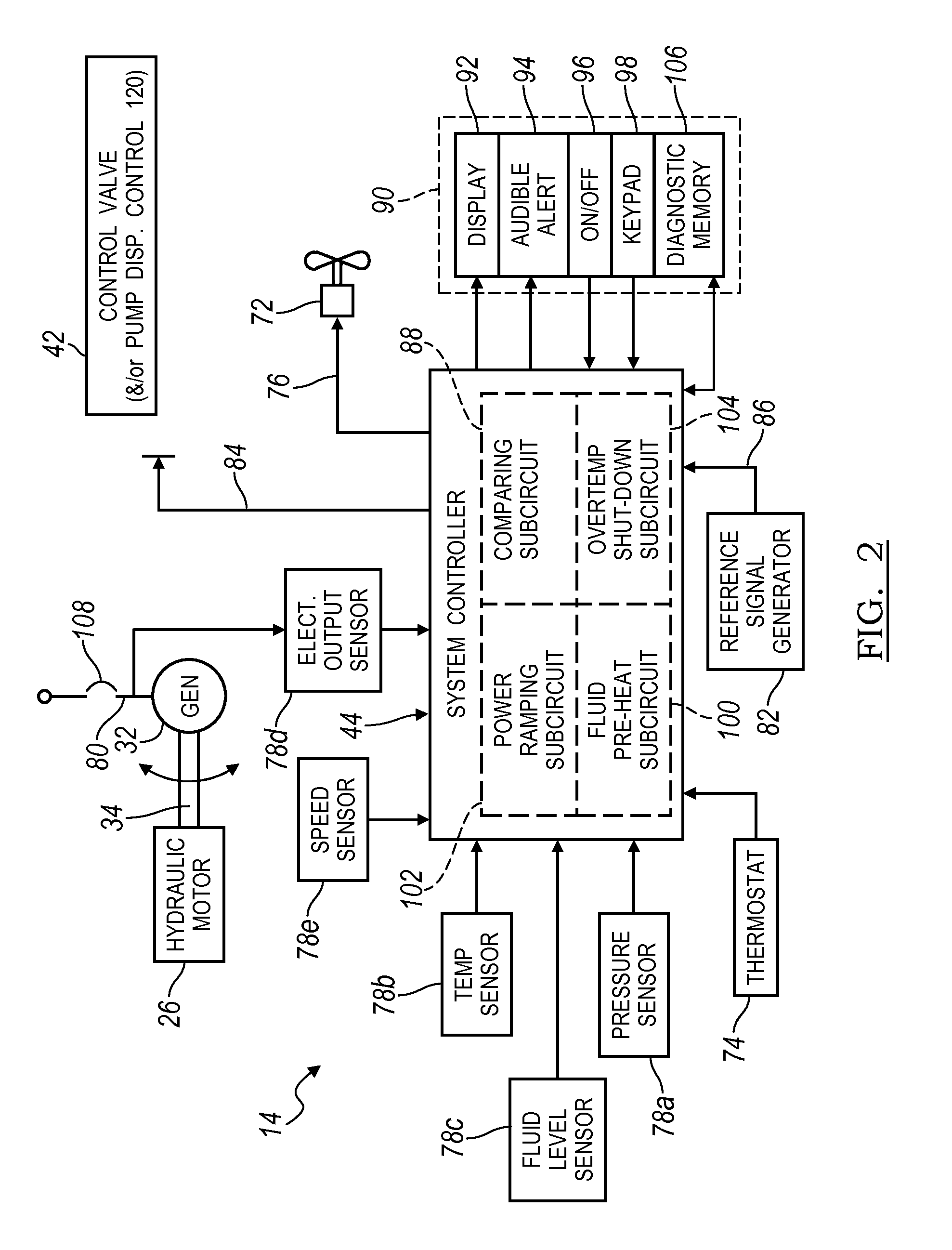
[0015]Moreover, the control circuit of the hydraulic control system may further include a temperature sensor disposed in the fluid circuit for sensing hydraulic fluid temperature. A system controller having a fluid pre-heating sub-circuit may be provided for generating a control signal controlling the valve assembly such that fluid is restricted from the hydraulic motor entirely until safe fluid temperature is obtained. Further, the system controller may further include a power ramping sub-circuit for generating a control signal controlling the valve assembly when sufficient fluid temperature is obtained such that power is supplied gradually to the hydraulic motor. The control circuit may include a temperature sensor disposed in the air intake for sensing ambient air temperature to be used in communication with the interface module for displaying a user alert of the temperature differential, aiding in recommended system installation to specifications.
[0016]Furthermore, the system controller may include an over-temperature shutdown sub-circuit for generating a control signal controlling the valve assembly when fluid temperature becomes too hot for safe operation such that fluid is restricted from the hydraulic motor thereby shutting down the auxiliary power source. Additionally, the control circuit can be equipped with an emergency override accessible by an operator for instructing the system controller to continue system operation when unsafe operating conditions exist. The system controller may include electrical communication for providing automatic shut down of user prioritized specific vehicle component AC power loads to alleviate overload or over-temperature conditions for maintaining safe operation of the power system. This communication can also alert the user of shut down requirements. The control circuit may include a sub-circuit for providing electrical communication to manually control a cooling fan by means of input from the interface module and can command the fan on and off through the user interface. The control circuit may further include a pressure sensor for determining system over-pressure, causing system operation to shutdown to prevent damage to hydraulic components.
[0024]Further, the method of operating the hydraulic control system may include preventing over-temperature damage to the hydraulic system when sensed fluid temperature exceeds safe operating temperature. Preventing over-temperature damage may involve annunciating the existence of over-temperature conditions to an operator when a first high temperature is obtained, triggering a timer to begin counting down a specified time when a second high temperature is obtained, and restricting all fluid flow to the motor when the timer has expired. Restricting all fluid flow to the motor can involve closing an electronically controlled hydraulic proportional valve disposed within the fluid circuit such that fluid is entirely restricted from the supply conduit. Additionally, the method may include overriding the restricting step upon receipt of an emergency override instruction from an operator to prevent shutdown and keep the system operating.
[0026]Furthermore, the hydraulic control system and generator can be arranged into a modular enclosure. This enclosure may direct cooling air in an upward or downward direction to provide efficient cooling and to reduce mounting space requirements. This modular enclosure could open grate mounted on the top surface of the unit that serves to allow air to exhaust in addition to providing a safe, non-slip walking surface. This modular enclosure may include a baffle to separate the cooler intake air from mixing with the warmer exhausted air. The fluid circuit supply and discharge hydraulic conduit can be disposed to exit the system in a generally downward direction in relation to the system mounting orientation to provide reduced mounting space requirements.

Problems solved by technology

However, numerous modules and devices for the vehicle as well as the engine require electrical power.
While this will indeed operate a generator, variations in engine speed will wreak havoc with characteristics of power output and therefore with equipment which is dependent upon stable voltage and frequency characteristics of electrical power.
However, such systems can have difficulty maintaining precise frequency output for controlling the most sensitive AC equipment and are often susceptible to premature mechanical failure.

Method used


Image

  • Electronic control for a hydraulically driven generator
  • Electronic control for a hydraulically driven generator
  • Electronic control for a hydraulically driven generator

Examples


Embodiment Construction

)

[0037]As required, detailed embodiments of the present invention are disclosed herein. However, it is to be understood that the disclosed embodiments are merely exemplary of an invention that may be embodied in various and alternative forms. Therefore, specific functional details disclosed herein are not to be interpreted as limiting, but merely as a representative basis for the claims and / or as a representative basis for teaching one skilled in the art to variously employ the present invention.

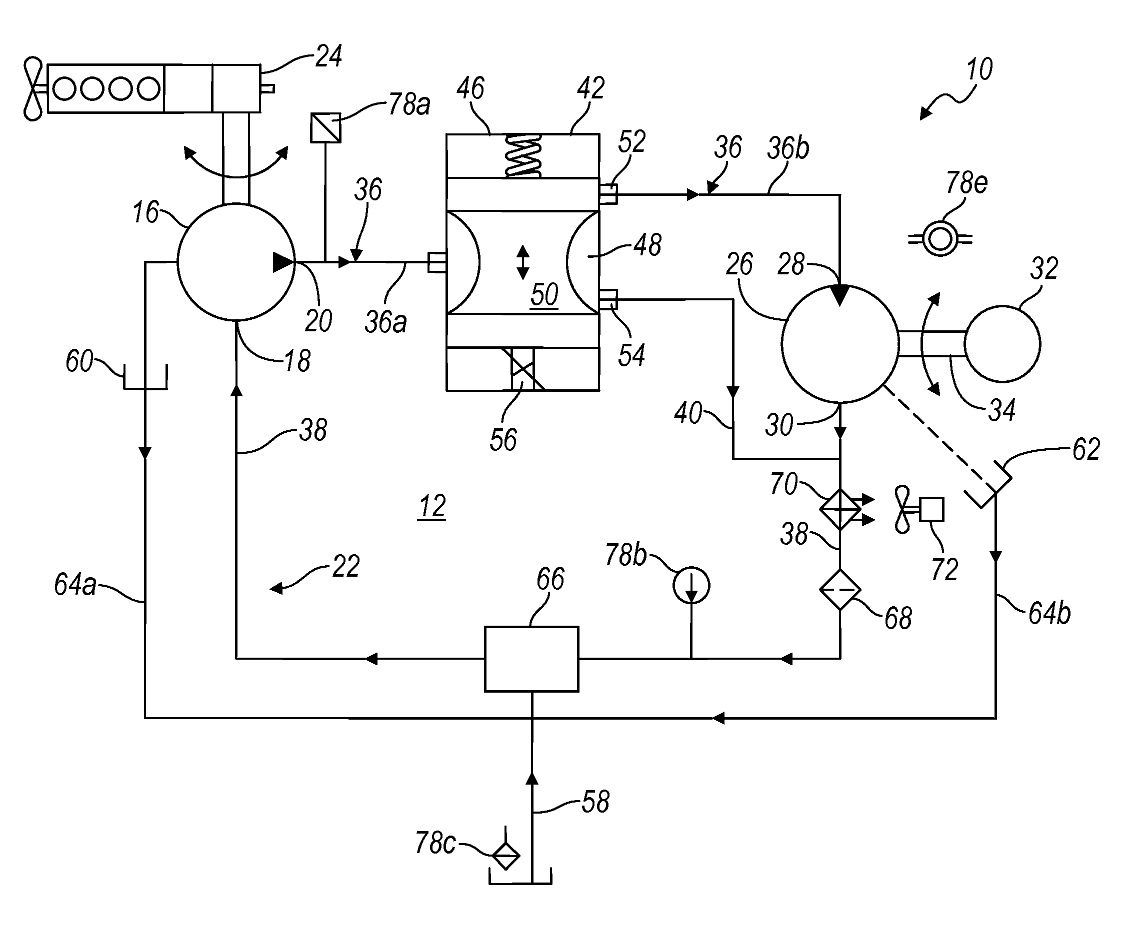
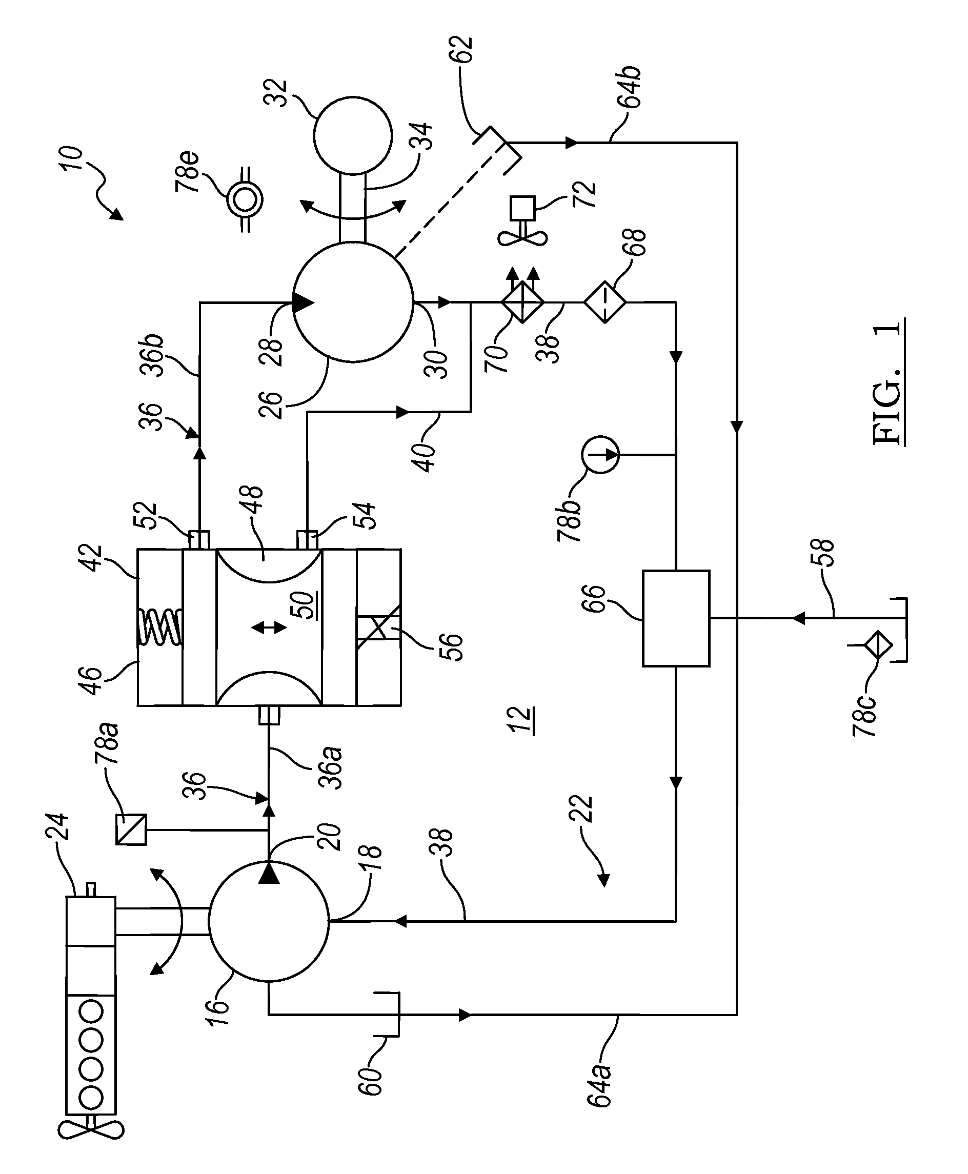
[0038]A hydraulic control system 10, according to an aspect of the present invention, is illustrated in FIGS. 1 and 2. FIG. 1 generally depicts a hydraulic circuit 12 for hydraulic control system 10, while FIG. 2 generally depicts a control circuit 14 for hydraulic control system 10.

[0039]Referring first to FIG. 1, hydraulic circuit 12 of system 10 is powered by a hydraulic pump 16, having an inlet 18 for receiving fluid for pumping and an outlet 20 for discharging pumped fluid under pressur...


PUM


Abstract

Electronic control for a hydraulic system to drive an auxiliary power source is provided, with an application as a system for controlling the operation of a hydraulically driven AC generator. The system includes a hydraulic pump, a hydraulic motor drivably connected to the generator, and a fluid circuit for circulating fluid from the pump to the motor and back. The feedback circuit contains a feedback conduit to feedback the motor. The system also includes a proportional servo control valve assembly for controlling the fluid conduits and a control circuit for controlling the control valve assembly to thereby control the flow of fluid to the motor. Sensors for measuring the operating parameters of the system and an operator interface module are both able to influence the operation of the system.

Description

CROSS-REFERENCE TO RELATED APPLICATIONS[0001]This is a continuation-in-part of U.S. application Ser. No. 12 / 324,025, filed Nov. 26, 2008 now U.S. Pat. No. 7,759,811; which is a continuation-in-part of U.S. application Ser. No. 11 / 275,574, filed Jan. 17, 2006, now U.S. Pat. No. 7,459,800.BACKGROUND OF THE INVENTION[0002]1. Field of the Invention[0003]The present invention is directed to an electronic control for hydraulic systems, and more particularly to precision control of hydraulically driven generators for stabilizing frequency and voltage output characteristics.[0004]2. Background Art[0005]Most engine driven vehicles utilize an internal combustion engine as the primary power source for propelling a vehicle. However, numerous modules and devices for the vehicle as well as the engine require electrical power. Typically, a rechargeable battery is provided with the vehicle as a basic power supply. The battery power supply system provides direct current (DC) electrical power for sta...

Claims


Application Information

Patent Timeline
Patent Type & Authority Patents(United States)
IPC IPC(8): F03B13/00F03B13/10H02P9/04
CPCF15B7/008F15B21/08F15B2211/20523F15B2211/20538F15B2211/40515F15B2211/413F15B2211/427F15B2211/45F15B2211/6333F15B2211/6336F15B2211/6343F15B2211/6656F15B2211/7058F16H61/4035F16H61/4043F16H61/4061F16H61/431F16H61/461F16H61/47H02P9/009H02P9/48H02P2101/30H02P2101/45
Inventor BOISVERT, MARIO P.KIENITZ, THOMASWASHELESKI, JOHN M.
Owner UUSI
Why Eureka
Try Eureka