
Binary hydraulic manifold system

a hydraulic manifold and binary technology, applied in the direction of centrifugal wheel fertilisers, ways, applications, etc., can solve the problems of hydraulic oil waste, hoses need to be removed, complicated maze of hydraulic lines and associated valves and other equipment, etc., to prevent oil loss, reduce labor costs, and easy change

Active Publication Date: 2014-09-30
SALFORD BBI
View PDF4 Cites 2 Cited by
  • Summary
  • Abstract
  • Description
  • Claims
  • Application Information

AI Technical Summary

Benefits of technology

[0005]The binary hydraulic manifold system of the present disclosure is designed to meet and overcome the aforementioned disadvantages of a typical or conventional spreader system. More particularly, the present binary hydraulic manifold system meets these needs. For example, all of the valves can be easily changed without loosening or removing any hydraulic hoses, thus preventing oil loss, reducing labor costs, and providing quick diagnosis of any performance issues. For example, if a valve fails during operation, it can be replaced easily and quickly by removing it from the binary manifold of the present system and replaced with a new valve. No hoses need to be loosened or removed to do so. Furthermore, if the user wishes to convert the spreader system of the present disclosure from manual control spreading to electronically controlled spreading, a manual cartridge that operates the particular circuit that is desired to be converted is easily removed and replaced by an electronically controlled valve. This conversion in the present system typically reduces installation time from four hours to less than one hour.
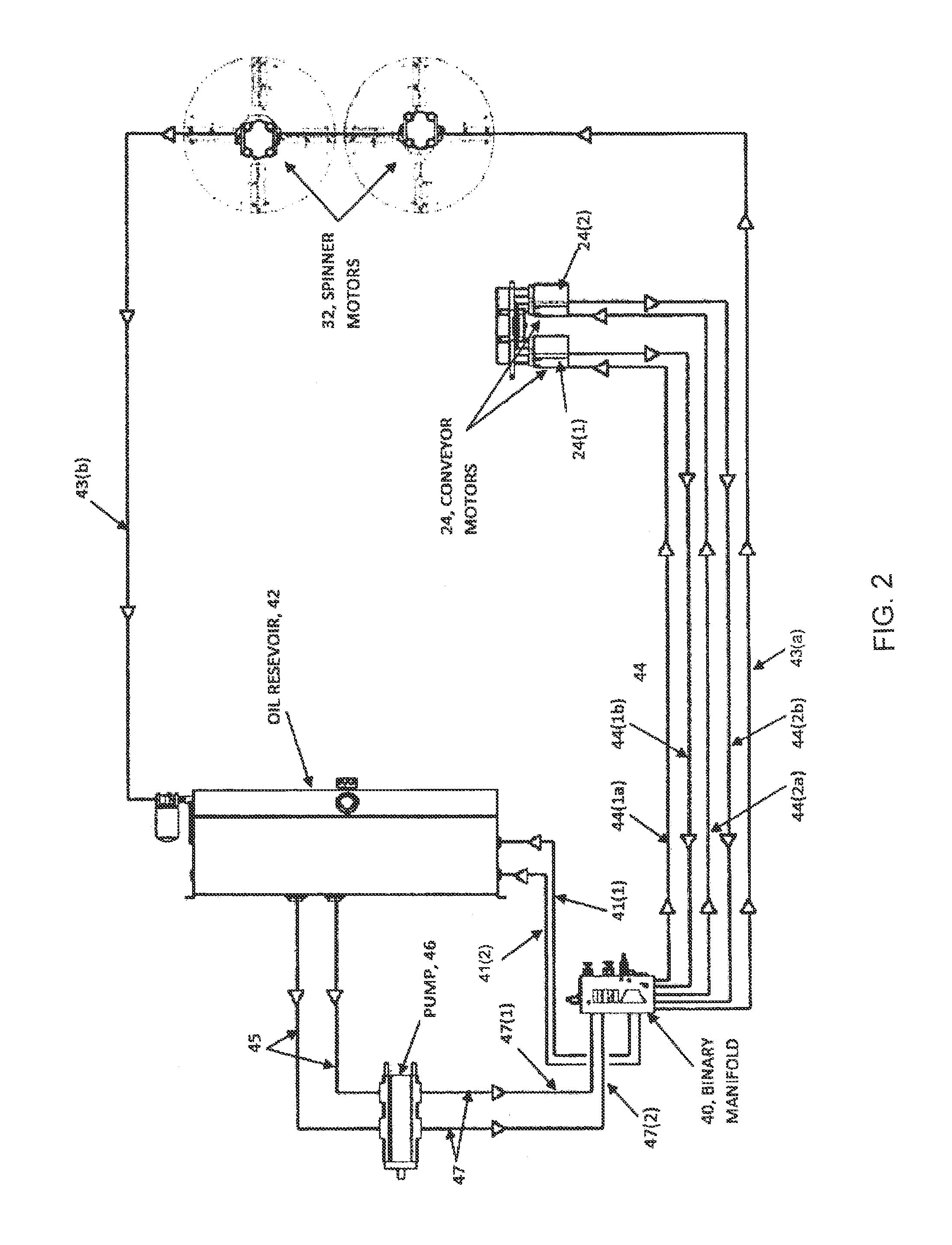
[0006]The binary hydraulic manifold system of the present disclosure accomplishes a plurality of functions within a single, unitary manifold. It allows for either manual control or electronic variable control of spreader conveyor speed and thus the rate of material to be applied and broadcast by the spreader. It also allows for either manual or electronic variable control of the speed of the spinners, thus controlling spread width of material broadcast by the spinners. Pressure relief for both the conveyer hydraulic circuit and spinner hydraulic circuit can be provided. A circuit which changes the oil flow from an in-series arrangement to parallel and back on command may also be provided which provides high output / low output control which when activated can double conveyor speed for very high output rates of material. This circuit also enables a high rate of output without increasing system pressures or higher rates of oil flow, thus maintaining low operating oil temperatures, greatly extending the life of the system.
[0007]Additionally, the system provides for on / off control of the conveyor(s) during normal operating conditions which may be used with or without electronic controls. This on / off function allows the conveyor(s) to be turned from an off condition to an on condition while also returning the speed of the conveyor(s) to the speed set prior to turning the conveyor(s) off. In the case of a conventional spreader, when the conveyor is turned back on from having been turned off, typically the speed of the conveyor has to be reset. The present system allows a conveyor to he turned on and operated on the same speed at which it was operating prior to being turned off without further or additional adjustment. This function increases the efficiency and efficacy of the applicator by allowing the spinners to continue running while the conveyor stops momentarily for the spreader to turn around at the end of the row and prepare for the next pass.
[0009]In another embodiment, the spreader can include at least two conveyors, and the variable speed control circuit for the at least two conveyors in the fluid manifold system further provides that flow of fluid through the variable speed conveyor circuit can be changed between in-parallel flow to a first and a second of the conveyors simultaneously and in-series flow where flow of fluid is sent to a first one of the conveyors and then sent from the first one of the conveyors to a second one of the conveyors. Changing the flow of fluid to in-parallel flow simultaneously to the at least two conveyors can allow the at least two conveyors to run at low speed with high torque relative to providing flow of fluid to the at least two conveyors in-series.

Problems solved by technology

They present a complicated maze of hydraulic lines and associated valves and other equipment for operating the hydraulic systems.
Maintenance of such systems is difficult and time consuming.
Should, for example, a valve or other associated equipment fail, typically hoses need to be removed consuming significant time and wasted hydraulic oil.
Diagnosis of performance issues can also be quite time consuming.

Method used


Image

  • Binary hydraulic manifold system
  • Binary hydraulic manifold system
  • Binary hydraulic manifold system

Examples


Embodiment Construction

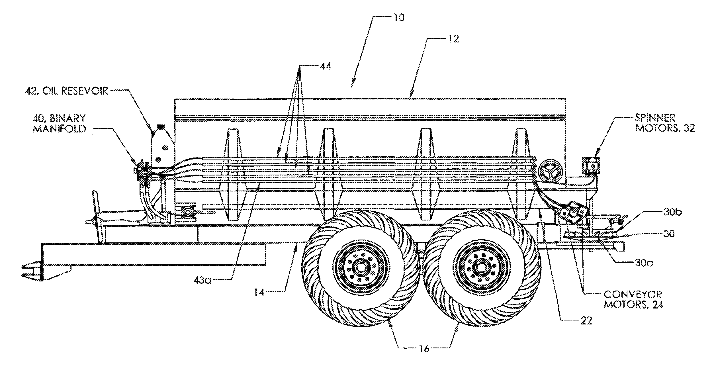
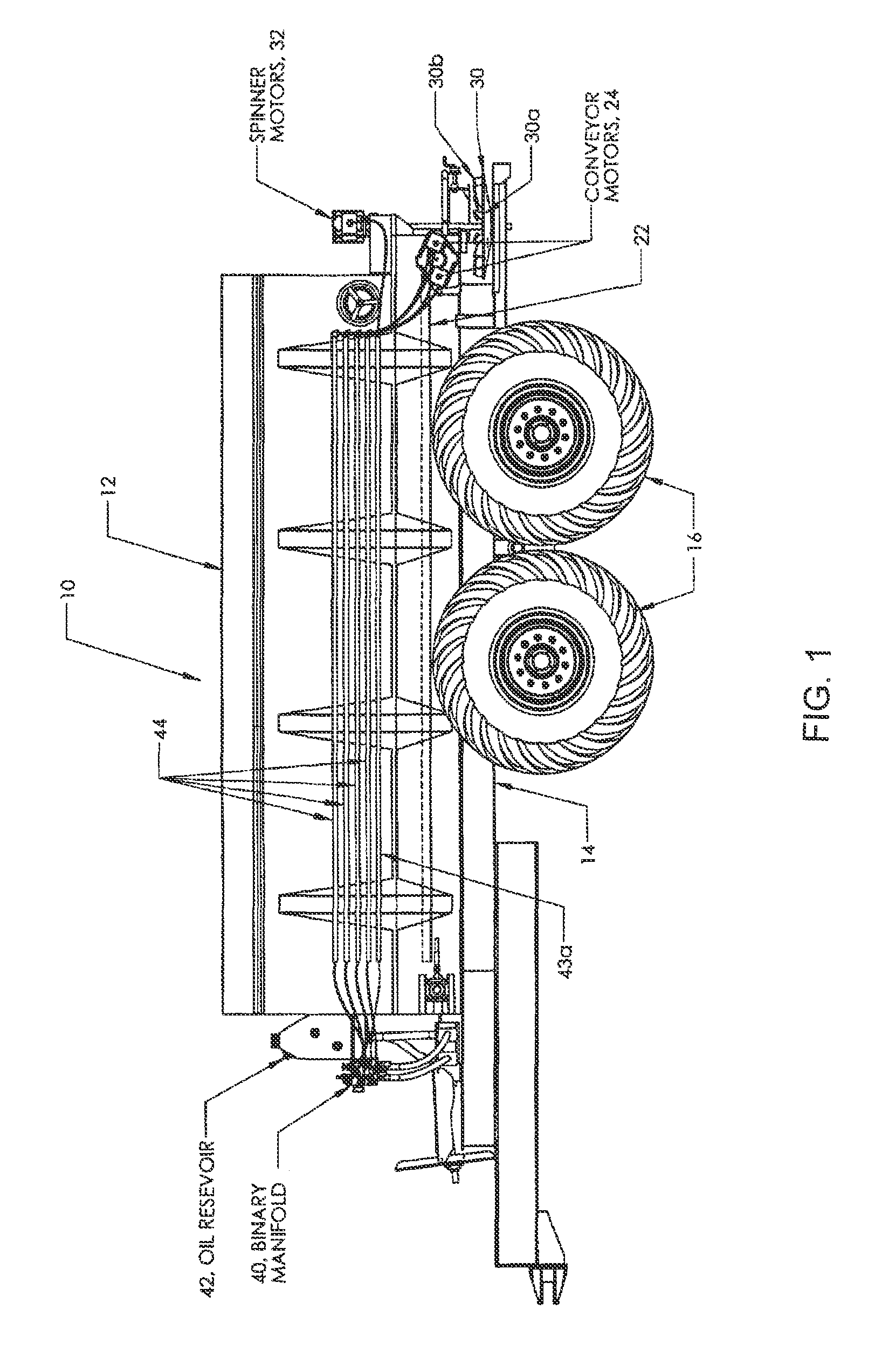
[0020]Referring more specifically to the drawings in which like reference numerals refer to like elements throughout the several views, an exemplary non-limiting embodiment of the binary hydraulic manifold system of the present disclosure is illustrated in FIGS. 1-4. Referring to FIG. 1, one embodiment of a spreader 10 of the present disclosure is illustrated. The spreader 10 includes one or more bins or hoppers 12 mounted on a mobile frame 14 carried by wheels 16. In one embodiment the wheeled frame is designed to be pulled by a tractor (not shown). Each bin or hopper has generally converging walls leading to a discharge port (not shown), allowing for gravitational feed and discharge of material ingredients contained within each respective bin or hopper to the conveyor(s). The bins or hoppers are generally designed for holding and discharging dry, bulk granular materials such as but not limited to fertilizer, fertilizer supplements, herbicides, insecticides, fungicides, soil pH adj...


PUM


Abstract

A hydraulic fluid manifold system for a spreader, the spreader including at least one bin for holding dry bulk material for distribution to at least one conveyor associated with the bin for receiving the dry bulk material from the at least one bin and transporting the dry bulk material to at least one spinner associated with the spreader. The hydraulic fluid manifold system includes a single, unitary manifold including a variable speed fluid control circuit for setting a speed for the at least one conveyor and a variable speed fluid control circuit for the at least one spinner of a spreader system for setting a speed for the at least one spinner, the variable speed control circuit for the at least one conveyor including an on / off device for the at least one conveyor that allows when fluid flow through the variable speed conveyor circuit to the at least one conveyor is turned on that the at least one conveyor can automatically operate at a speed set for the at least one conveyor prior to fluid flow to the at least one conveyor having been turned off. Further, the spreader can include at least two conveyors, and the variable speed control circuit for the at least two conveyors can further include flow of hydraulic fluid through the variable speed conveyor circuit to be changed between in-parallel flow to a first and a second of the conveyors simultaneously and in-series flow where flow of fluid is sent to a first one of the conveyors and then sent from the first one of the conveyors to a second one of the two conveyors.

Description

CROSS-REFERENCE TO RELATED APPLICATION[0001]This application claims priority to and the benefit of U.S. provisional application entitled, “Binary Hydraulic Manifold System,” having Ser. No. 61 / 354,804, filed Jun. 15, 2010, which is entirely incorporated herein by reference.FIELD OF THE DISCLOSURE[0002]The present disclosure relates to a spreader system of the type used to distribute one or more material ingredients, such as dry bulk material, for example fertilizer and fertilizer supplements, compost, poultry litter, gravel, sand and other granular materials, and broadcast them over a ground surface such as an agricultural field, road or other surfaces.BACKGROUND OF THE DISCLOSURE[0003]It is generally known to provide a spreader system for spreading or broadcasting ingredients, such as fertilizer and fertilizer supplements, organics, sand and other granular materials over a ground surface. A conventional spreader has one or more bins or hoppers for holding dry bulk material for dist...

Claims


Application Information

Patent Timeline
Patent Type & Authority Patents(United States)
IPC IPC(8): A01C17/00F17D3/00
CPCF17D3/00Y10T137/86493A01C19/00
Inventor OWENBY, STEVECHIPMAN, MICHAELBATTLE, TED
Owner SALFORD BBI
Learn More