Discharge controller

a discharge controller and discharge controller technology, applied in the direction of indicating/monitoring circuits, electrical generators, transportation and packaging, etc., can solve problems such as abnormal heat generation or excess current, and achieve the effect of easy extension of the battery life of a system including a plurality of cells

Active Publication Date: 2013-09-26
ENVISION AESC ENERGY DEVICES LTD
View PDF5 Cites 2 Cited by
  • Summary
  • Abstract
  • Description
  • Claims
  • Application Information

AI Technical Summary

Benefits of technology

[0022]As described above, according to the present invention, the battery life of a system including a plurality of cells can be easily extended.

Problems solved by technology

A large cross current can cause excess current or abnormal heat generation.

Method used


Image

  • Discharge controller
  • Discharge controller
  • Discharge controller

Examples


Embodiment Construction

[0032]In recent years, a “degradation region” in which degradation of a lithium-ion cell is promoted in an intermediate region of the lithium-ion cell (the region from the upper limit to the lower limit of the discharge capacity in which the cell can supply power) has been discovered. Such a degradation region is noticeably recognized in lithium-ion cells with manganese-based positive electrodes in particular. Data that has been collected indicates that passage through the degradation region promotes degradation of a cell when the cell is discharged and discharge capacity remaining in the cell is being reduced.

[0033]In the present invention, this degradation region is utilized when the degrees of degradation of a plurality of cells are adjusted to each other in order to extend the battery life of the system.

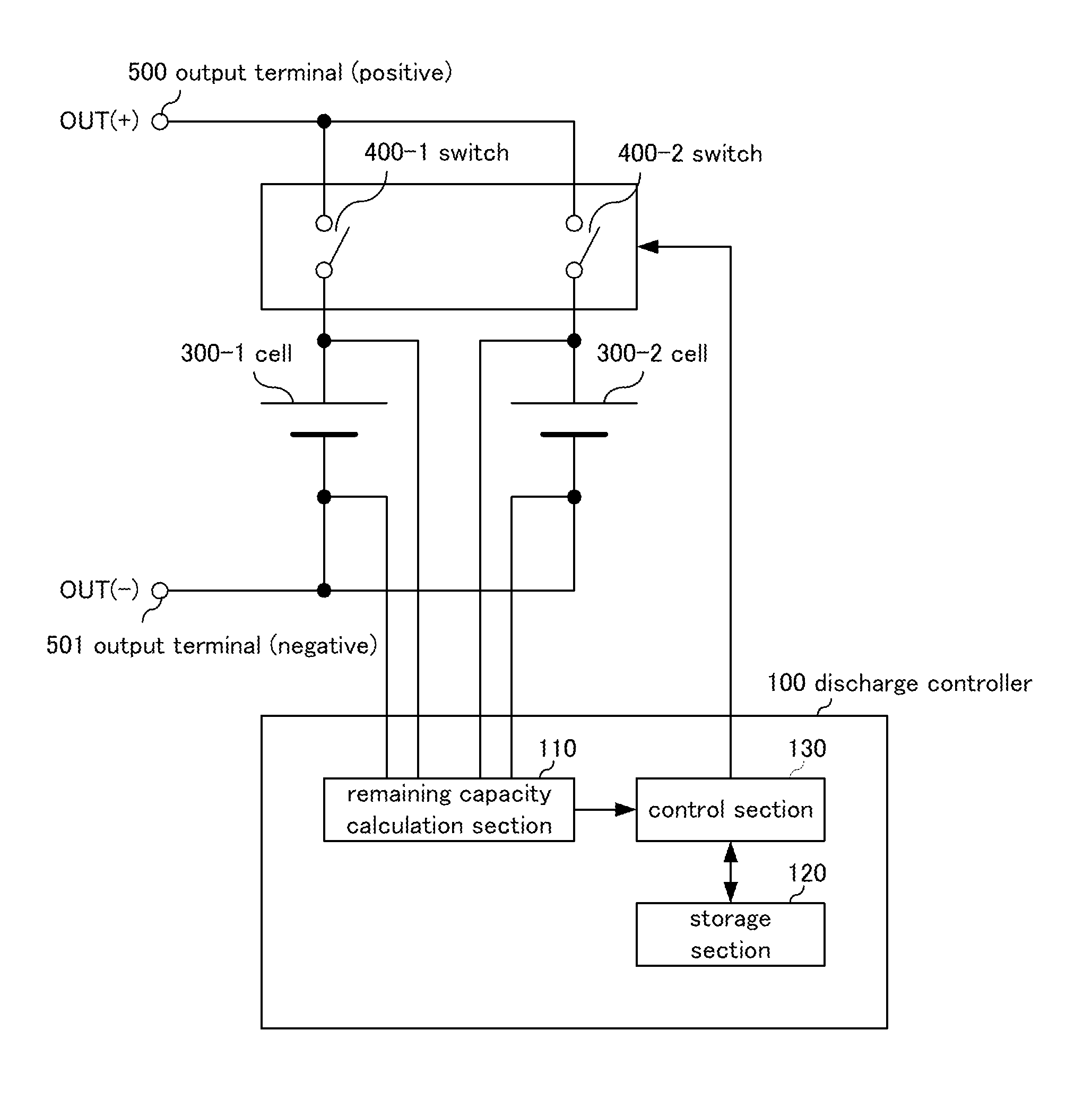
[0034]An exemplary embodiment will be described below with reference to the drawings.

[0035]FIG. 1 is a diagram showing an exemplary embodiment of a discharge controller of the pr...


PUM


Abstract

Remaining capacity calculation section (110) calculates the remaining capacity for each of cells (300-1) and (300-2) connected in parallel with each other, and control section (130) stops discharge of the first cell from cells (300-1) and (300-2), whose remaining capacity calculated by remaining capacity calculation section (110), has become equal to a threshold value stored in storage section (120) after the start of discharge of cells (300-1) and (300-2).

Description

TECHNICAL FIELD[0001]The present invention relates to a discharge controller, a discharge control method and a program for controlling discharge of cells.BACKGROUND ART[0002]In recent years, in various fields, there have been growing concerns about environmental problems.[0003]With these concerns, in the field of electric power supply, certain approaches to power supply such as photovoltaic (PV) power generation and use of secondary cells used in electric vehicles (EVs) and hybrid EVs (HEVs) have attracted attention. Lithium-ion secondary cells are considered promising in such secondary cells. It is expected that lead storage cells will be replaced with Lithium-ion secondary cells in response to widespread use thereof in the future.[0004]As a rule, connecting an old cell (having a small discharge capacity, a high degree of degradation) and a new cell (having a larger discharge capacity, a low degree of degradation) in parallel with each other should be avoided. This is for the purpo...

Claims


Application Information

Patent Timeline
Patent Type & Authority Applications(United States)
IPC IPC(8): H02J7/00
CPCH01M10/441H01M10/482H02J7/0021H02J2007/0067Y02T10/7055H02J7/0068H02J7/0063Y02T10/70Y02E60/10H02J7/0013H02J7/0048H02J7/007182
Inventor SUZUKI, SHIN
Owner ENVISION AESC ENERGY DEVICES LTD
Why Eureka
Try Eureka