
A trolley line that can provide power supply for rotary rail change

A trolley line and rotating guide rail technology, applied in the field of trolley line, can solve problems such as the inability to meet the simultaneous operation of multiple cages, and achieve the effects of high work efficiency, improved conveying efficiency, and stable operation

Active Publication Date: 2022-05-24
三明市金达机电设备有限公司
View PDF7 Cites 0 Cited by
  • Summary
  • Abstract
  • Description
  • Claims
  • Application Information

AI Technical Summary

Problems solved by technology

However, this invention has not proposed a specific design scheme for the trolley line during the track change process, nor can it meet the needs of simultaneous operation of multiple cages

Method used


Image

  • A trolley line that can provide power supply for rotary rail change
  • A trolley line that can provide power supply for rotary rail change
  • A trolley line that can provide power supply for rotary rail change

Examples


Embodiment Construction

[0042] In order to describe the technical content, structural features, achieved objects and effects of the technical solution in detail, the following detailed description is given in conjunction with the specific embodiments and the accompanying drawings.

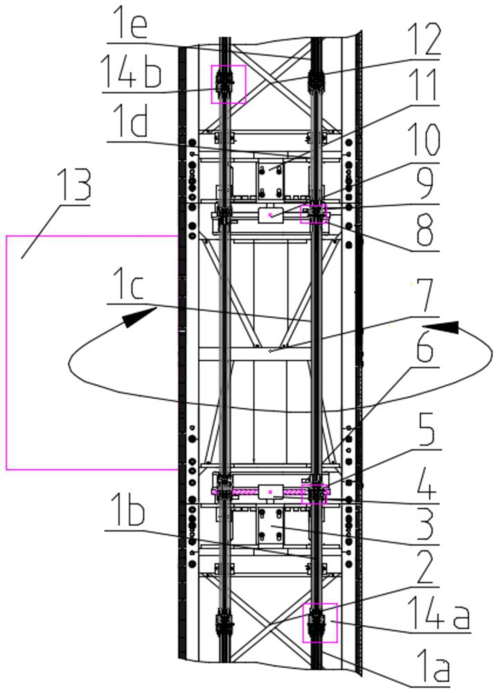
[0043] see figure 1 , this embodiment provides a trolley line that can provide power supply for rotating rails, the trolley line is multi-strand in use and is installed symmetrically at 180 degrees relative to the rotation center. Each trolley line is a multi-segment structure, and is specifically composed of a first power supply point trolley line 1a, a lower end trolley line 1b of the rotary joint, a lower fixed section 14a, a lower end trolley line roller 6, and a slewing joint power supply trolley line. 1c, the first lower transition rotary joint 5, the upper end sliding contact line 1d of the rotary joint, the upper end sliding contact line roller 9, the first upper transition rotary joint 8, the upper fixed joint 14...


PUM


Abstract

The invention relates to a trolley line that can provide power supply for rotating rails. In use, it is multi-strand and installed symmetrically at 180 degrees relative to the rotation center, and each strand is a multi-stage structure. Specifically, the trolley line at the first power supply point , lower fixed section, trolley line at the lower end of the swivel section, trolley line roller at the lower end, the first lower transition swivel joint, power supply trolley line at the swivel section, trolley line at the upper end of the swivel section, trolley line roller at the upper end, first upper transition rotation Section, the upper fixed section and the second power supply point trolley line. The sliding contact line of the rotating ladder is symmetrically installed on the front and rear sides of the first rotating bracket to ensure that the sliding contact line at the front rotates 180° with the rotating guide rail and can be aligned with the upper and lower sliding contact lines at the rear end, so that the cage can perform a 180-degree track as required transform. Due to the modular design, multiple cages can be used at the same time to improve the conveying efficiency. The use of multi-section power supply points can ensure that each cage can operate independently and avoid each other. Compared with the traditional left and right double cage configuration structural scheme in the whole system, the present invention saves time and effort, and has high work efficiency.

Description

technical field [0001] The invention relates to the technical field of trolley wire devices for construction elevators, in particular to a trolley wire that can provide power supply for rotating rails. Background technique [0002] The existing construction hoists are mainly used for straight up and down in the vertical direction, and they are both left and right double-cage configuration structures, which require multiple reciprocating loading and unloading of goods in transportation operations, and the loading and unloading efficiency of goods is low. To this end, Chinese patent CN 201510124152.7 proposes a rotating rail changing device, including a fixed frame body, a rotating frame body and a track, the relative rotation of the fixed frame body and the rotating frame body is realized by using a slewing bearing, and is locked or locked by a rotary locking device. Release the rotational frame body degrees of freedom. The invention solves the problem that the existing rack...

Claims


Application Information

Patent Timeline
Patent Type & Authority Patents(China)
IPC IPC(8): B66B7/06H01R41/00
CPCB66B7/064H01R41/00
Inventor 陈玉彪陈振坤沙懋华江旗
Owner 三明市金达机电设备有限公司
Learn More