Deflection coil and its making method
A technology of deflection yoke and manufacturing method, which is applied to the manufacture of magnetic deflection devices, electrode devices, and related components, and can solve the problems of being sandwiched between two plate-shaped ribs 1d, damage to the starting end of winding 2s, and assembling operations of deflection yokes Increase and other issues
- Summary
- Abstract
- Description
- Claims
- Application Information
AI Technical Summary
Problems solved by technology
Method used
Image

Examples
no. 1 approach
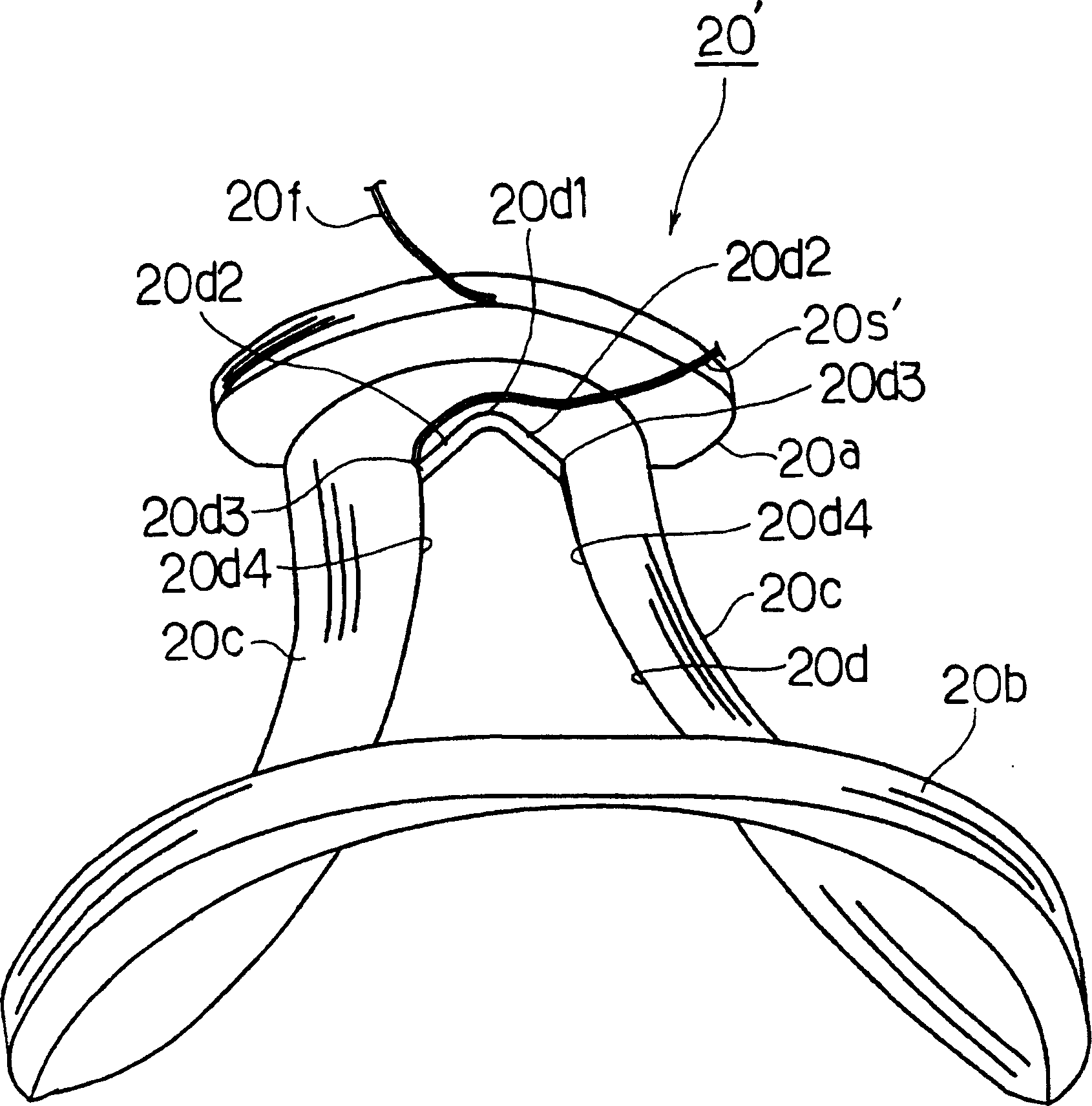
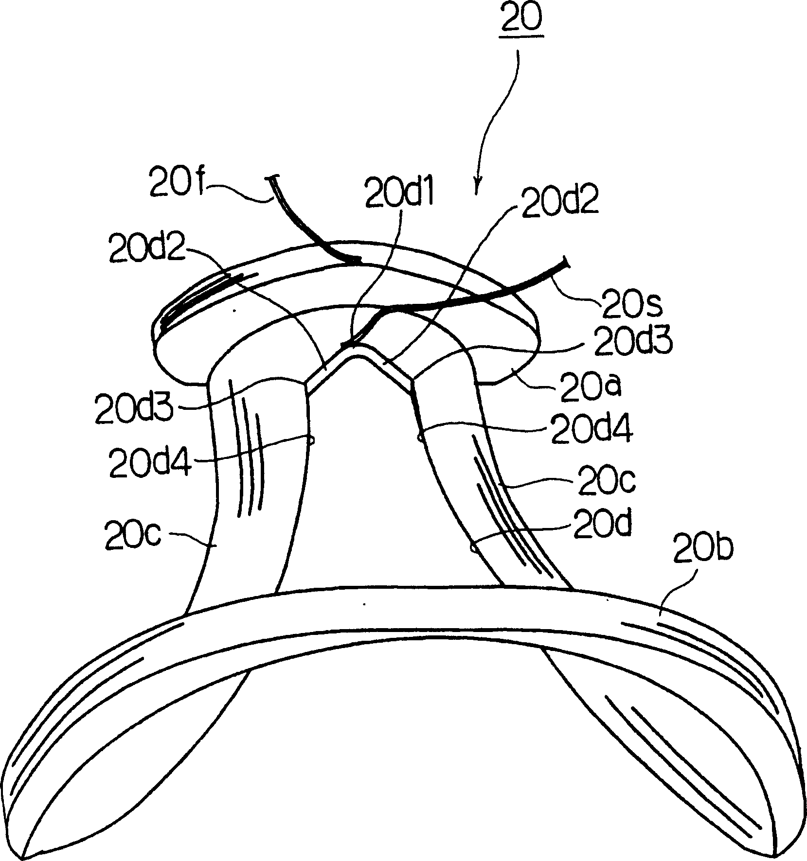
[0037] First, an example of the overall configuration of the deflection yoke of the present invention will be described. exist Figure 5 Among them, the deflection coil forms one side ( Figure 5 The lower side in the middle) has a larger diameter, while the other side ( Figure 5 The upper side of the middle) funnel-shaped with a smaller diameter. Among them, the larger diameter part is the screen side of the cathode ray tube, and the smaller diameter part is the journal side. Bearing housing 1 is made of resin such as denatured PPE (polyphenylene ether) or PP (polypropylene). Flanges 1a, 1b are formed on the small-diameter side and the large-diameter side of the bearing housing 1, respectively.
[0038] A pair of saddle-shaped horizontal deflection coils 20' are installed on the inner side of the bearing housing 1, and a pair of saddle-shaped vertical deflection coils 3 are installed on the outer side. The bearing housing 1 keeps the horizontal deflection coils 20' and t...
no. 2 approach
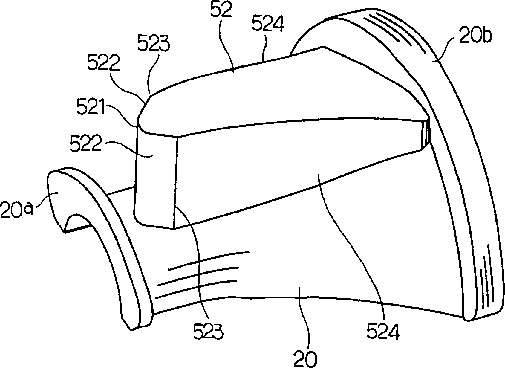
[0061] In the first embodiment described above, the bent portion 20d3 was used as a method of increasing the resistance when the wire is peeled off, but other methods may also be used. Figure 10 The horizontal deflection coil 21' of the second embodiment is partially shown. The horizontal deflection coil 21' is in a state after stripping the wires. The shape of the horizontal deflection coil 21' and Figure 12 The horizontal deflection coil 2 shown is the same. The horizontal deflection coil 21' is constituted by a small-diameter portion 21a, a large-diameter portion (not shown), and two side portions 21c, and a central portion is constituted by a window portion 21d. exist Figure 10 Among them, 21f is the ending end of the winding, and 21s' is the starting end of the winding from which the wire has been stripped. An adhesive tape 60 is wound around one side portion 21c.
[0062] The starting end of the winding before stripping the wire is called 21s. When pulling the wi...
no. 3 approach
[0064] Figure 11 The horizontal deflection coil 22' of the third embodiment is partially shown. The horizontal deflection coil 22' is in a state after stripping the wires. The shape of the horizontal deflection coil 22' is the same as Figure 12 The horizontal deflection coil 2 shown is the same. The horizontal deflection coil 22' is composed of a small-diameter portion 22a, a large-diameter portion (not shown), and two side portions 22c, and a central portion is composed of a window portion 22d. exist Figure 11 Among them, 22f is the ending end of the winding, and 22s' is the starting end of the winding from which the wire has been stripped. Such as Figure 11 As shown, a recessed portion 70 is formed where it is desired to stop wire stripping. The function of the concave portion 70 is also to increase the resistance when the wire is stripped.
[0065] The recessed portion 70 can be easily formed by placing a pin during the winding process or after the winding is comp...
PUM
 Abstract
Description
Claims
Application Information
 - R&D
- Intellectual Property
- Life Sciences
- Materials
- Tech Scout
- Unparalleled Data Quality
- Higher Quality Content
- 60% Fewer Hallucinations
Browse by: Latest US Patents, China's latest patents, Technical Efficacy Thesaurus, Application Domain, Technology Topic, Popular Technical Reports.
© 2025 PatSnap. All rights reserved.Legal|Privacy policy|Modern Slavery Act Transparency Statement|Sitemap|About US| Contact US: help@patsnap.com