Supercharge Your Innovation With Domain-Expert AI Agents!

Crank shaft and method for manufacturing same

A crankshaft and axis technology, which is applied in the manufacturing field of crankshafts composed of multiple pieces, can solve problems such as abandonment, high tolerances of the main shaft and crankpin being parallel to each other, and failure.

Inactive Publication Date: 2005-04-13
PANTHER MACHINE
View PDF0 Cites 0 Cited by
  • Summary
  • Abstract
  • Description
  • Claims
  • Application Information

AI Technical Summary

Problems solved by technology

[0006] A major disadvantage of this known multi-piece crankshaft is that the main shaft and the crank pin must be parallel to each other to a very high tolerance.
However, during pressurization operations, the main shaft and crankpin are often misaligned relative to each other, so that the resulting crankshaft assembly must either be corrected by bending the crank pin and main shaft relative to each other, or in some cases is discarded as scrap
Additionally, these prior art crankshafts also fail when pushing out and twisting the main shaft relative to the counterweight

Method used


Image

  • Crank shaft and method for manufacturing same
  • Crank shaft and method for manufacturing same
  • Crank shaft and method for manufacturing same

Examples


Embodiment Construction

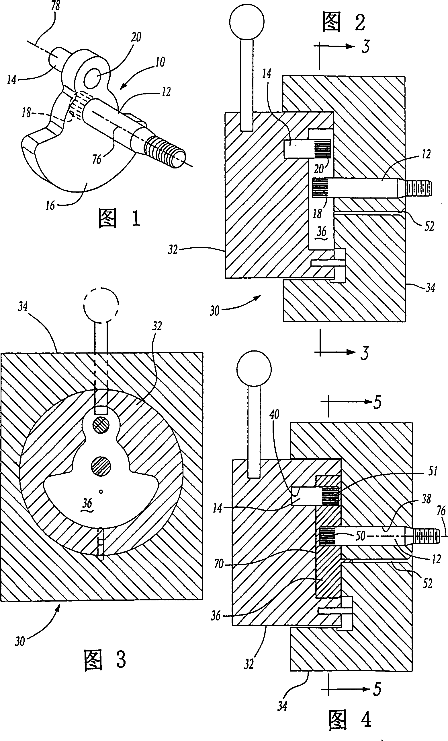
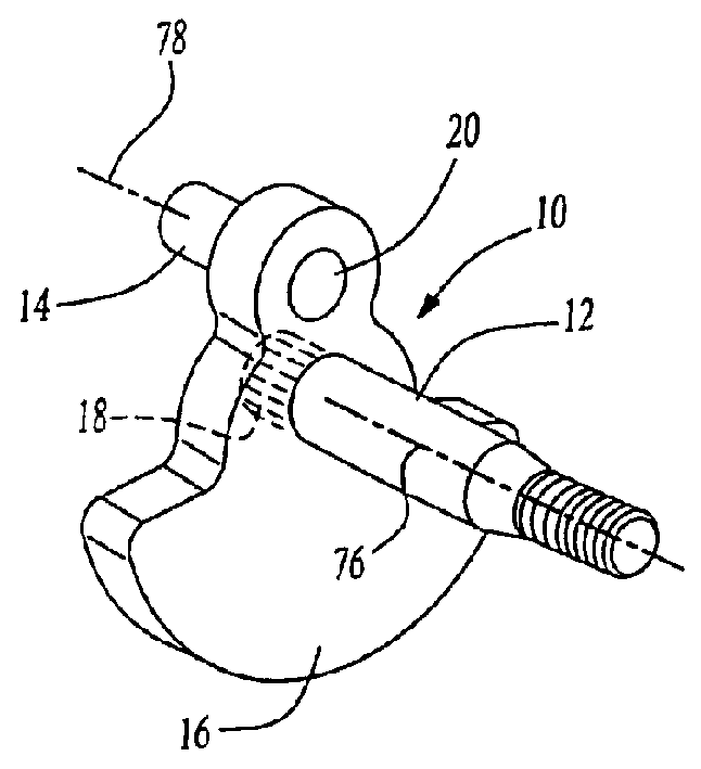
[0018] Referring to Figure 1, a preferred embodiment of the crankshaft 10 of the present invention is shown. The crankshaft has an elongated main shaft 12 adapted for rotation about its longitudinal axis and a crankpin 14 whose longitudinal axis is parallel to but radially spaced from the main shaft 12 .

[0019] A counterweight 16 extends between an end 18 of the main shaft 12 and an end 20 of the crank pin 14 . A counterweight 16 secures the crankpin 14 and main shaft 12 together in well known fashion.

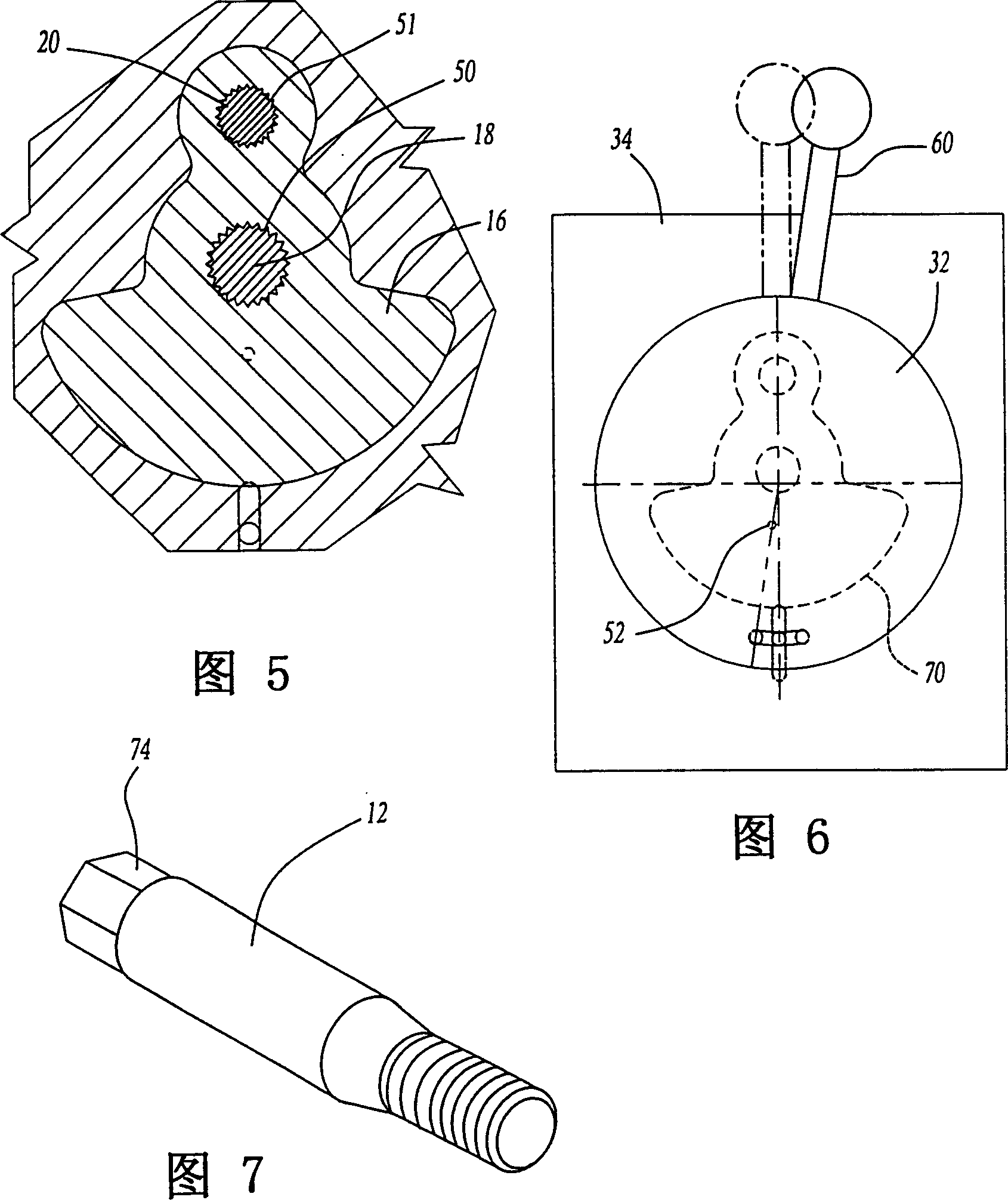
[0020] Referring now to FIGS. 2-4, the crankshaft of the present invention is formed by casting a thermosetting material, preferably a liquid metal such as zinc, around the aligned ends 20 and 18 of the crank pin 14 and main shaft 12 during casting of the counterweight 16. 10. As best shown in FIG. 2, model 30 has two half-moulds 32 and 34 which are movable in a closed position shown in solid lines in FIG. 2 and an open position shown in dashed lines. When the molded part...


PUM


Abstract

A multi-piece crankshaft is disclosed having a main shaft having two ends rotatable about its axis, a crankpin also having two ends and an axis parallel to but radially spaced from the axis of the main shaft , and at least one counterweight between one end of the main shaft and one end of the crank pin, the counter weight is formed by casting a liquid metal around the main shaft and crank pin in the mold cavity.

Description

technical field [0001] This invention relates generally to crankshafts and, more particularly, to methods and apparatus for the manufacture of the multi-piece crankshafts. Background technique [0002] A conventional crankshaft consists of a segmented main shaft whose axis coincides with the crankshaft's axis of rotation. One or more crank pins are located at radially spaced apart but parallel to the main shaft. A piston is fixed to each crankpin which rotationally drives the crankshaft about its axis of rotation. [0003] Since the crankpin is radially offset from the axis of rotation of the crankshaft and is coupled to a piston, a counterweight is traditionally provided in securing the mainshaft to the crankpin to allow the entire crankshaft to rotate in balance. In many known crankshafts, the entire crankshaft is machined from a single, heavy metal casting, whereby the main shaft, crankpin and counterweights are of one-piece construction. However, machining such a cran...

Claims


Application Information

Patent Timeline
Patent Type & Authority Patents(China)
IPC IPC(8): F16C3/10
Inventor 唐纳德·G.·利思
Owner PANTHER MACHINE
Features
  • R&D
  • Intellectual Property
  • Life Sciences
  • Materials
  • Tech Scout
  • Unparalleled Data Quality
  • Higher Quality Content
  • 60% Fewer Hallucinations
Learn More