Reduplicative positioning hydraulic machine control device

A technology of control devices and tools, which is applied in the direction of fluid pressure actuation devices, lifting devices, accumulator devices, etc., can solve the problems of difficult sealing, complicated disposal, and difficulty in repeatedly being in place without load, so as to achieve punctual and reliable sealing Effect

Inactive Publication Date: 2005-06-01
胡宣哲
View PDF0 Cites 0 Cited by
  • Summary
  • Abstract
  • Description
  • Claims
  • Application Information

AI Technical Summary

Problems solved by technology

[0002] The disclosed 991152379 "hydraulic jacking equipment automatic device" and 001133020 "automatic hydraulic jack" have the following disadvantages: the stored energy is difficult to achieve no-load repeated positioning; The one-way valve realizes the control, and its sealing is difficult; the automatic positioning of the oil cylinder, on the one hand, relies on the spring force to lift the piston in place, and quickly absorbs oil from the oil tank, and on the other hand, it relies on the accumulator to release energy, and the pressure drop of the piston reaches (recovery) position, quickly drain oil to the fuel tank, a large amount of oil enters and exits quickly from the fuel tank, and its breathing port is required to be particularly unblocked. When the machine is turned upside down, oil cannot escape from the breathing port, resulting in complicated disposal

Method used


Image

  • Reduplicative positioning hydraulic machine control device
  • Reduplicative positioning hydraulic machine control device
  • Reduplicative positioning hydraulic machine control device

Examples


Embodiment Construction

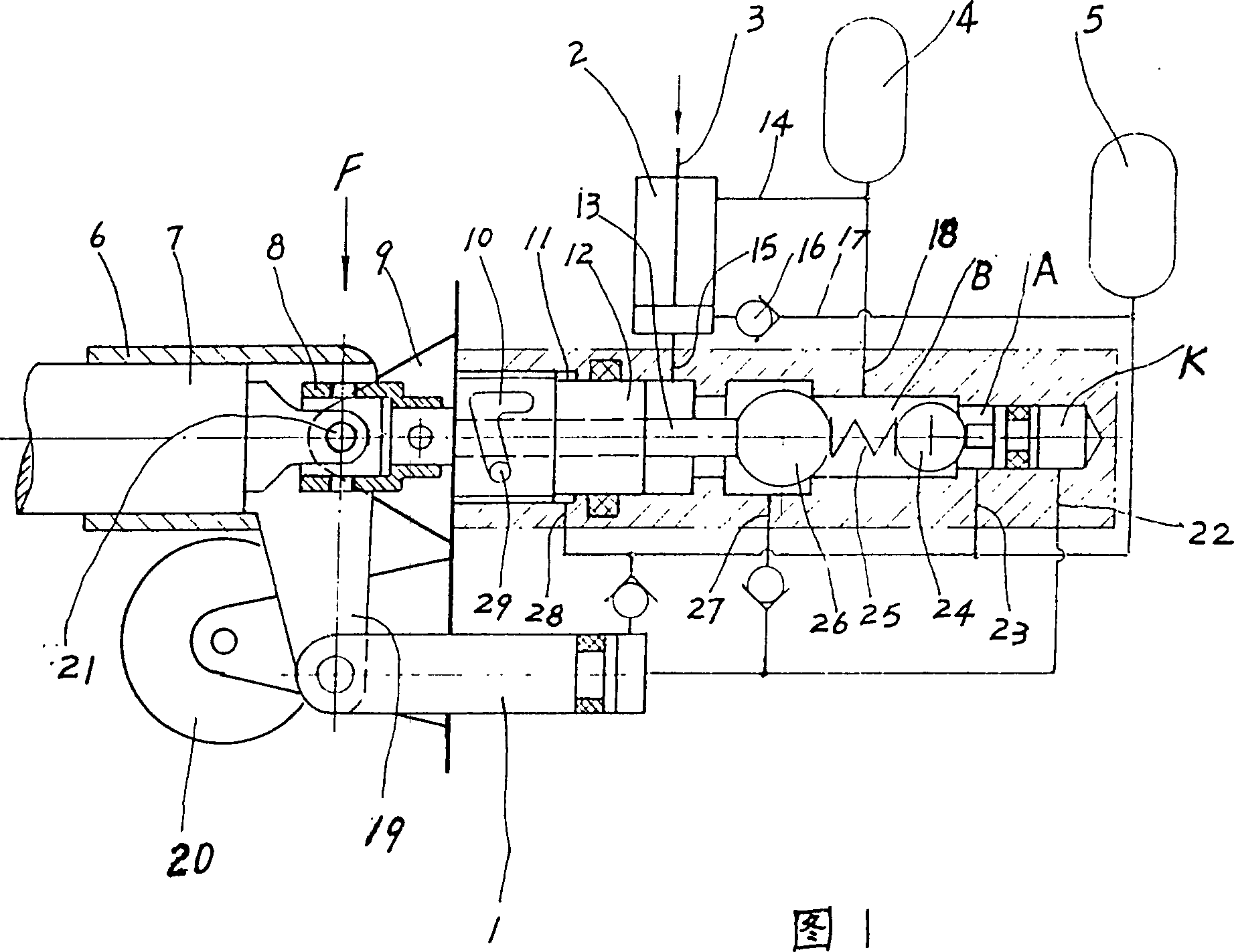
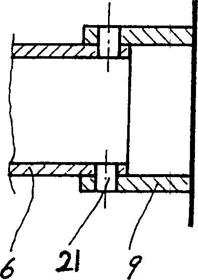
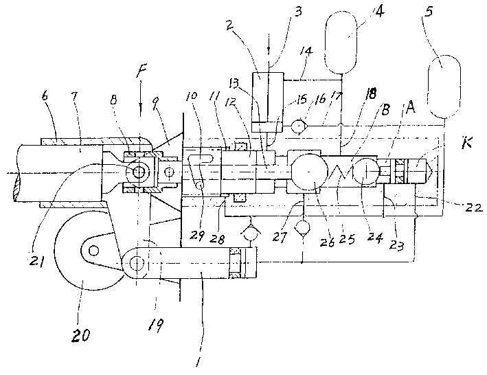
[0010] With reference to the accompanying drawings, one consists of an oil pump 1, an oil cylinder 2, a piston 3, a high-pressure stage accumulator 4, a low-pressure stage accumulator 5, and a two-position two-way oil return rotary valve 12, a double-control check valve 26, and a hydraulic control valve. The combined control device of the one-way valve 24 constitutes the full hydraulic implement of the present invention. The accumulator 4 communicates with the upper cavity of the oil cylinder 2 through the channel 14; the accumulator 5 communicates with the lower cavity of the oil cylinder 2 through the channel 17 and the one-way valve 16. In the oil return rotary valve 12 in the control device, the large diameter of the valve core is connected with the valve body through threads, and the small diameter is closely matched with the valve body. There is a hook-shaped groove 10 on the valve core cylinder, and the center is a through hole. Cooperate with a push rod 13. A spring 2...


PUM


Abstract

The utility model relates to a control device for repeatedly in place hydraulic equipment, which is composed of a two-position two-way oil return rotary valve, a double control one-way valve and a hydraulic control one-way valve. The lower chamber of the oil cylinder of the device is provided with a low-pressure accumulator, and the upper chamber of the oil cylinder is provided with a high-pressure accumulator. The operating handle is placed in a handle pipe seat, which is provided with a universal coupling capable of controlling the oil return rotary valve, and a power arm for driving the oil pump is fixed on the handle pipe seat. Because the present invention has high and low-pressure accumulators, when the high-pressure accumulator releases energy to the upper chamber of the oil cylinder and the pressure drop piston is in place, the oil in the lower chamber enters the low-pressure accumulator to store energy and is used to lift the piston again. It realizes full hydraulic automatic position, and there is no oil leakage problem at the breathing port of the fuel tank. The control device composed of oil return rotary valve and two one-way valves has reliable sealing on time. The pump and valve are jointly controlled, and the operating handle can make the oil pump arbitrarily supply oil to the upper and lower chambers of the oil cylinder, realizing repeated positioning without load.

Description

technical field [0001] The invention relates to a hydraulic implement control device for jacking loads. Background technique [0002] The disclosed 991152379 "hydraulic jacking equipment automatic device" and 001133020 "automatic hydraulic jack" have the following disadvantages: the stored energy is difficult to achieve no-load repeated positioning; The one-way valve realizes the control, and its sealing is difficult; the automatic positioning of the oil cylinder, on the one hand, relies on the spring force to lift the piston in place, and quickly absorbs oil from the oil tank, and on the other hand, it relies on the accumulator to release energy, and the pressure drop of the piston reaches (recovery) Position, quickly drain oil to the fuel tank, a large amount of oil quickly enters and exits from the fuel tank, and its breathing port is required to be particularly unblocked. When the machine is turned upside down, oil cannot escape from the breathing port, resulting in comp...

Claims


Application Information

Patent Timeline
Patent Type & Authority Patents(China)
IPC IPC(8): B66F3/28B66F3/42F15B1/02F15B21/14
CPCB66F3/28B66F3/42F15B1/024F15B21/14
Inventor 胡真华胡爱武胡宣哲
Owner 胡宣哲
Why Eureka
Try Eureka