A bearing normal pressure self-air sealing device

A sealing device and hermetic sealing technology, applied in the field of bearing sealing, can solve problems such as sliding friction that easily generates heat, increase equipment investment, and waste inert gas, so as to reduce maintenance costs and raw material consumption, improve equipment utilization, and reduce bearing temperature. Effect of liter and power loss

Inactive Publication Date: 2016-06-15
NANYANG NORMAL UNIV
View PDF7 Cites 0 Cited by
  • Summary
  • Abstract
  • Description
  • Claims
  • Application Information

AI Technical Summary

Problems solved by technology

The first and second methods cannot solve the problem of "sliding friction is easy to generate heat, waste power and easily damage friction parts". It can still be used for reactions that only require low-speed stirring, but for those that require high-speed stirring React simply cannot be used
The third method, for the inert gas protection reaction, continuously feeds the inert gas. Although it can solve the problem of high-speed stirring reaction, it faces a large amount of inert gas waste. It is necessary to avoid the waste of inert gas, or for products and reactants containing toxic substances. of volatile substances, the third method is powerless
As an improvement of the third method, adding an inert gas circulation device can reduce the waste of inert gas, but at the same time increases equipment investment

Method used


Image

  • A bearing normal pressure self-air sealing device
  • A bearing normal pressure self-air sealing device
  • A bearing normal pressure self-air sealing device

Examples


Embodiment 1

[0034] For example, the application number is CN201410342664.6 which discloses a high-shear grinding reactor. High-speed operation is a key parameter. The sealing method adopted is to continuously feed inert gas or reaction gas. This method is used as a laboratory reaction It is acceptable to waste a little inert gas or non-toxic reaction raw material gas (such as carbon dioxide), but it is obviously not cost-effective for industrial production. Applying the present invention to a "high-shear grinding reactor" is very suitable for reactions in which the internal and external pressures of the reactor are all within the range of normal pressure. The specific operation process is as follows:

[0035] 1. Installation and docking of equipment

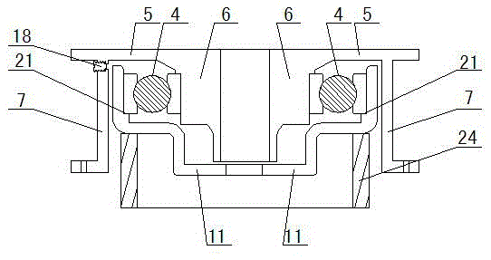
[0036] 1. If image 3 , let the opening of the shaft lip A11 face up, and place it on the ring bracket 24, first assemble the bearing 4 on the shaft lip A11, and then install the inner lip 6 of the bottom plate on the inner sleeve of the b...

Embodiment 2

[0050] Spherical nano-calcium carbonate has many uses, and its production method is mostly prepared by reacting slaked lime (calcium hydroxide) and carbon dioxide with water as the solvent.

[0051] The equipment docking of this embodiment is the same as that of Embodiment 1, and the reaction operation is as follows:

[0052] 1. If Figure 4 , connecting the air inlet 30 to a carbon dioxide gas source whose outlet pressure is normal pressure.

[0053] 2. Start the stirring device. According to the reaction needs, open the valve at the cooling water inlet 26, add metered powdery calcium hydroxide through the solid feed port 29, and open the valve at the air inlet 30 to add carbon dioxide.

[0054] 3. Check the pH value of the reaction solution through the solid feeding port 29, and close the valve of the air inlet 30 when the pH value is 5.

[0055] 4. Open the discharge port 33, discharge the material, and continue post-processing the semi-finished nano-calcium carbonate emu...

Embodiment 3

[0058] The device docking of this embodiment, such as Figure 5 , except that the bottom plate 5 of the present invention 25 and the reactor top cover 3 are directly fixed together by bolts, then the reactor top cover 3 is fixed to the reactor by bolts, and the lower end of the stirring shaft 1 is installed with a stirring paddle 38 Except, all the other are with embodiment 1. In this embodiment, the reactor is wrapped with a heating jacket 37 filled with heating oil. The heating jacket 37 is provided with an electric heating tube 47 and an electric heating jacket temperature probe 40. One end of the heating jacket 37 is provided with a heating oil feeding port 39, and the other end A heating jacket vent pipe 44 is provided, and an insulating layer 45 is provided outside the heating jacket 37; a cooling pipe inlet 41, a reaction liquid temperature probe 42 and a cooling pipe outlet 43 are arranged in the reactor, and an input gas port 35 is provided at the upper end of the rea...


PUM


Abstract

A normal-temperature self-gas-sealing device for a bearing comprises a static seal part, a movable seal part and the bearing. The static seal part comprises a bearing pedestal bottom cover and a bearing pedestal upper cover. The bearing pedestal bottom cover is composed of a bottom plate inner lip part, a bottom plate outer lip part and a bottom plate. The bearing pedestal upper cover is composed of an upper cover inner lip part, an upper cover outer lip part and a connection plate. The upper cover outer lip part and the bottom plate outer lip part are connected in an extending manner. A lubrication chamber used for storing lubricating oil is formed between the bearing pedestal bottom cover and the bearing pedestal upper cover. The movable seal part comprises a shaft lip part A and a shaft lip part B which are arranged on a stirring shaft in a sleeving manner. The shaft lip part A is located between the bottom plate inner lip part and the bottom plate outer lip part in the radial direction. The shaft lip part A, the bottom plate outer lip part and the upper cover outer lip part are buckled in a staggered manner in the axial direction. The shaft lip part B and the upper cover inner lip part are buckled in a staggered manner in the axial direction. The upper cover inner lip part is located in the shaft lip part B. The bearing is located between the bottom plate inner lip part and the shaft lip part A in the radial direction. The normal-temperature self-gas-sealing device can be suitable for high-sped or low-speed stirring reactions and can be suitable for both inert gas shielding reactions and reaction systems with toxic and harmful gas.

Description

technical field [0001] The invention relates to the technical field of bearing sealing, in particular to a bearing normal pressure self-air sealing device. Background technique [0002] In the field of chemical industry, it is often faced with the problem of chemical reactions at atmospheric pressure that require both stirring and hermetic sealing. For example, inert gas protection reactions, or products and reactants containing toxic and volatile substances, or non-toxic but inexpensive volatile reactants or products, all require a relatively independent reaction space, and at the same time require Stir. For this problem, there are currently three methods: one is to install a shaft sealing device outside the bearing; the other is to install a sealing device with a sealing lip between the inner and outer bearings; the third is to continuously feed the reaction system Inert gas, so as to achieve the purpose of air-tight reaction or inert gas protection under stirring condit...

Claims


Application Information

Patent Timeline
Patent Type & Authority Patents(China)
IPC IPC(8): F16J15/324F16J15/3232F16C35/00
CPCF16C35/00F16J15/3232
Inventor 王利亚刘宗才李森兰赵洁汪彩露王建平
Owner NANYANG NORMAL UNIV
Why Eureka
Try Eureka