
Fluid storage supplementing device and hydraulic system

A fluid and hydraulic pump technology, used in fluid pressure actuation devices, servo motors, servo motor components, etc., can solve problems such as unsuitability for hydraulic systems and oil leakage, achieve light weight, ensure stable working conditions, and improve working life. Effect

Inactive Publication Date: 2020-12-01
北京羿升动力科技有限公司
View PDF2 Cites 1 Cited by
  • Summary
  • Abstract
  • Description
  • Claims
  • Application Information

AI Technical Summary

Problems solved by technology

This technical solution uses a leak-proof sleeve device to avoid oil overflow in the fuel tank. However, if the device rolls over, there will still be oil leakage. It is not suitable for hydraulic systems equipped with aircraft and bionic robots that have violent fuselage swing movements.

Method used


Image

  • Fluid storage supplementing device and hydraulic system
  • Fluid storage supplementing device and hydraulic system
  • Fluid storage supplementing device and hydraulic system

Examples


Embodiment 1

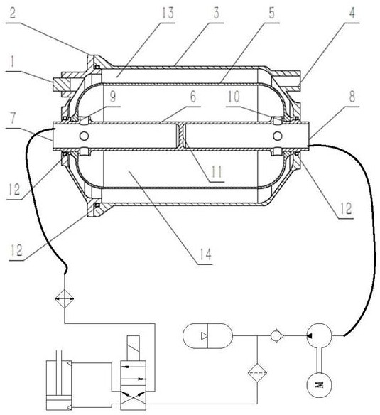
[0051] figure 2 It is an open hydraulic system with a valve-controlled hydraulic cylinder, in which the device of the present invention replaces the traditional hydraulic oil tank, the return oil of the hydraulic system is connected to the oil return port 7 of the device, and the oil suction port of the hydraulic pump is connected to the The oil suction port 8 of the device is connected. The return oil of the hydraulic system enters the soft capsule 5 of the device through the oil return port 7 for storage. Simultaneously, the hydraulic pump sucks the fluid therein from the soft bag 5, and since the soft bag 5 isolates the fluid from the outside air, the hydraulic pump can stably suck the fluid no matter how the system swings upside down.

Embodiment 2

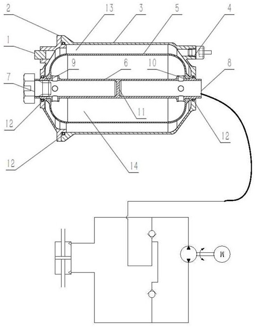
[0053] image 3 It is a closed hydraulic system, and the hydraulic pump drives the hydraulic cylinder to expand or contract through bidirectional rotation. The device replaces the role of the charge pump and is used to replenish oil in the closed hydraulic system. The oil return port 7 of the device is blocked with a cap or a plug during operation to prevent fluid leakage. A one-way valve needs to be installed on the vent hole 4, and a certain amount of compressed gas is injected into the outer cavity 13 through the one-way valve. , the compressed gas forms a certain pressure in the outer chamber 13, and the pressure squeezes the fluid therein to the oil suction port 8 through the soft capsule 5, forming a certain pressure in the oil suction port 8. When the closed hydraulic system loses a certain amount of fluid due to leakage during operation, causing the pressure in the hydraulic system pipeline to be lower than the pressure in the oil suction port 8, the fluid stored in t...

Embodiment 3

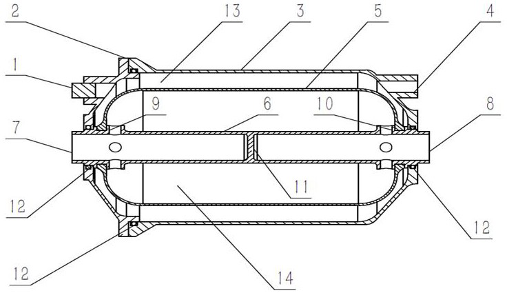
[0055] Figure 4 for figure 1 The difference between the alternative solution and the technical solution introduced before is that the central pipeline 6 is a straight-through pipeline, and there is no partition 11 between the oil return port 7 and the oil suction port 8 . In the original scheme, the function of the partition 11 is to prolong the path of the fluid flowing from the oil return port 7 to the oil suction port 8, and help the fluid to separate out the gas dissolved therein. However, if the working condition of the hydraulic system is moderate, the amount of gas dissolved in the fluid is small, or the device is used for oil replenishment, then the separator 11 may not exist.


PUM


Abstract

The invention provides a fluid storage supplementing device and a hydraulic system. The fluid storage supplementing device comprises a shell, a soft bag is arranged in the shell, a central pipeline penetrates through the soft bag, the two ends, penetrating out of the soft bag, of the central pipeline are provided with an oil return port and an oil suction port respectively, an outer cavity is formed between the inner wall of the shell and the outer wall of the soft bag, and an inner cavity is formed between the inner wall of the soft bag and the outer wall of the central pipeline; an oil inlethole communicated with the inner cavity is formed in the position, close to the oil return port, of the central pipeline section reserved in the soft bag, and an oil outlet hole communicated with theinner cavity is formed in the position, close to the oil suction port, of the central pipeline section reserved in the soft bag. No matter what posture the device swings and reverses, the fluid stored in the device cannot leak out, and stable fluid supply can be kept for the hydraulic pump all the time. The fluid storage supplementing device is particularly suitable for being applied to hydraulicsystems carried by aircrafts, bionic robots and the like with violent fuselage posture swinging motion.

Description

technical field [0001] The invention relates to the field of hydraulic oil tanks, in particular to a fluid storage replenishment device and a hydraulic system. Background technique [0002] The attitude of the traditional hydraulic oil tank cannot be greatly changed during operation. If the attitude of the hydraulic oil tank is turned upside down, so that the outlet connecting the tank and the suction port of the hydraulic pump is exposed outside the liquid surface, the hydraulic pump will suck in air. A large amount of air is mixed into the fluid of the hydraulic system, causing cavitation of the hydraulic components, oxidation of the fluid, and reduction of the incompressibility of the fluid, which greatly damages the operating performance and quality of the system. At the same time, because the traditional hydraulic oil tank has a vent to keep it connected to the atmospheric pressure, if the hydraulic oil tank is turned upside down, a certain amount of fluid will leak fro...

Claims


Application Information

Patent Timeline
IPC IPC(8): F15B1/08F15B11/08F15B13/02
CPCF15B1/08F15B11/08F15B13/02
Inventor 张旭
Owner 北京羿升动力科技有限公司
Learn More