Platen Assembly, Molding System and Method for Platen Orientation and Alignment

a platen and molding technology, applied in the field of mechanical devices, can solve the problems of rework or rejection of molded parts, exacerbate mold wear, and large molds, and achieve the effects of improving mold alignment, improving mold alignment, and increasing the weight of the overall platen design

Active Publication Date: 2008-07-24
HUSKY INJECTION MOLDING SYST LTD
View PDF11 Cites 40 Cited by
  • Summary
  • Abstract
  • Description
  • Claims
  • Application Information

AI Technical Summary

Benefits of technology

[0021]In a preferred embodiment, the anti-tilt apparatus functions to provide automatic correction to changes in alignment of the mold halves arising from sagging and tilting events.
[0024]Advantageously, the present invention provides improved alignment of complementary molds halves mounted on respective platens. Moreover, the present invention provides a platen anti-tilting mechanism that compensates for mold weight and mold overhang and which mechanism can be applied both to the moving and stationary platens. The present invention, furthermore, finds particular utility with platen designs in which the front face of the platen is free-floating since the present invention beneficially improves mold alignment without significantly adding to the weight of the overall platen design.
[0025]Additionally, a preferred embodiment of the present invention is adaptive and can compensate for platen tilting caused by a mold stroke forces. In this way, this particular embodiment improves alignment of both mold and related mold components (e.g. cores and leader pins) throughout the entire cycle and therefore reduces the amount of wear experienced by the mold and its related components. With decreased wear and increased alignment, the present invention therefore extends the potential working life of the mold / clamp unit assembly and reduces servicing and maintenance costs.

Problems solved by technology

Where alignment is poor, there is excessive mold wear during mold closing and mold flash can occur during injection (which results in re-work or rejection of the molded parts).
Furthermore, the flashed material, if left on the mold sealing surfaces, can cause or otherwise exacerbate mold wear.
By their very nature and function and as a consequence of the high pressure molding environments in which they operate, molds are materially and structurally massive.
Particularly in large tonnage application, each mold can weigh many tens of tons.
When such a heavy mold is mounted to a platen, the centre of gravity of the entire composite assembly shifts because the overhanging nature of the mold half alters the distribution of mass (relative to the mold mounting face and the platen on its own) and thus induces a bending (and more particularly a tilting) moment into the composite assembly.
Consequently, when the mold is closed, the resultant tilting or sagging produces a fundamental misalignment between the mold halves.
This misalignment causes mold wear and has a detrimental effect on part quality, as previously described.
Even when the foot extension is significant (in terms of overall length), the weight of the mold not only has the effect of causing a shifting of the mold downwardly, but it also induces tilting and misalignment of the front mold mounting face.
Furthermore, the momentum associated with moving a heavy mass effectively increases / decreases the effective bending moment, thereby causing the platen to experience some perturbation (especially visible at the top of the platen).
However, any overhanging mass of the mold half has the detrimental effects of: i) causing the mold to drop under its own weight and particularly the action of shear stresses; and ii) varying the effective centre of gravity for the combined mold and platen assembly to cause sagging / tilting (from the resultant bending moment) of the combined platen-mold assembly.
Box-structure designs have no free-floating front face and are less effective in preventing platen deflection under applied clamp tonnage.
However, the use of heavyweight molds (that could have masses in excess of 80 tons) still induces tilting or bending of the platen and thus misalignment between the mold halves.
Unfortunately, while these are alternative solutions, the increase in steel material significantly increases overall raw material costs for the platen.
An increased technical specification also leads to an overall cost increase.
The resultant tilting of the stationary platen produces additional misalignment that places strains on components that are within the mold.
For example, the misalignment causes damage to cores or leader pins during the opening of the mold and which extend outwardly from one or both of the mold halves.
Damage caused to such cores or leader pins can prevent effective mold alignment with the effect that the mold (or a specific cavity within the mold) begins to exude flash or otherwise to wear prematurely.
Twisting or tilting of the platen cannot, however, be addressed by merely adjusting the height of the moving platen.
The prior art is generally unable to address inertia problems and, furthermore, is applicable to set-up conditions only.
Also, the prior art does not address for tilting of the platen that arises from the mounting of heavy molds, but rather just looks to provide basic mold half alignment through rudimentary level control of the platen at set-up.

Method used


Image

  • Platen Assembly, Molding System and Method for Platen Orientation and Alignment
  • Platen Assembly, Molding System and Method for Platen Orientation and Alignment
  • Platen Assembly, Molding System and Method for Platen Orientation and Alignment

Examples


Embodiment Construction

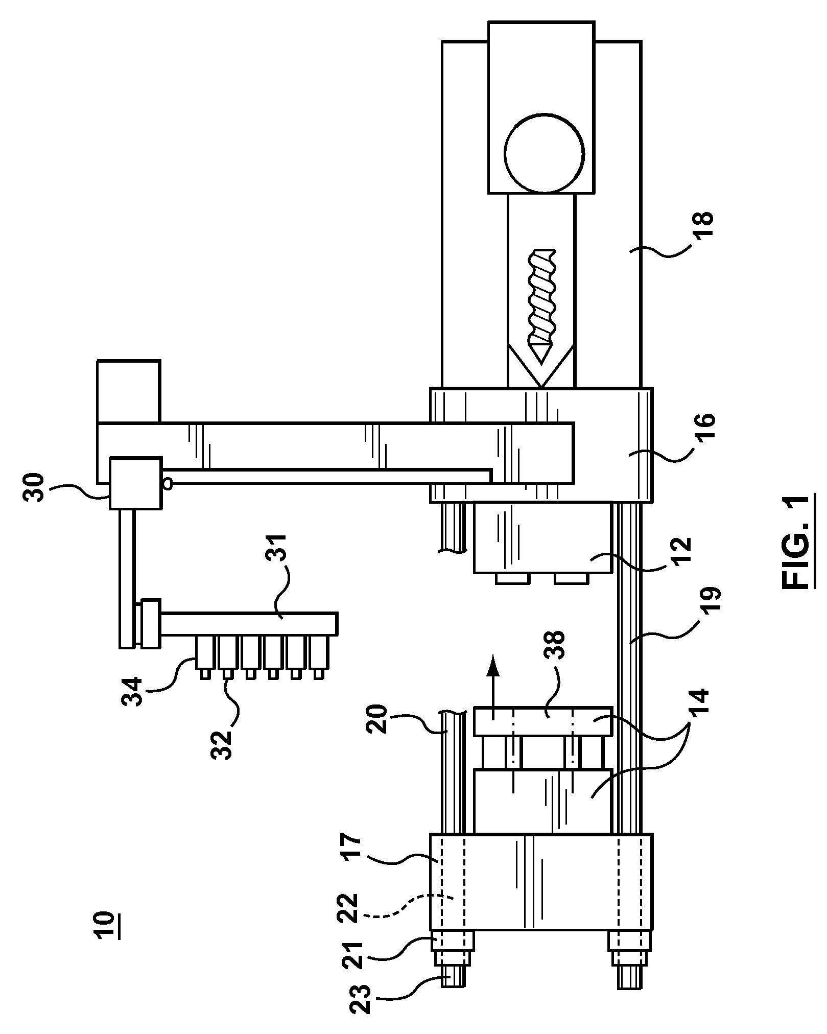
[0035]FIG. 1 shows a typical injection molding machine 10 that can be adaptable to support platen anti-tilt mechanism according to the various embodiments of the present invention.

[0036]Like conventional machines, during each injection cycle, the molding machine 10 produces a number of plastic parts corresponding to a mold cavity or cavities defined by complementary mold halves 12, 14 located within the machine 10.

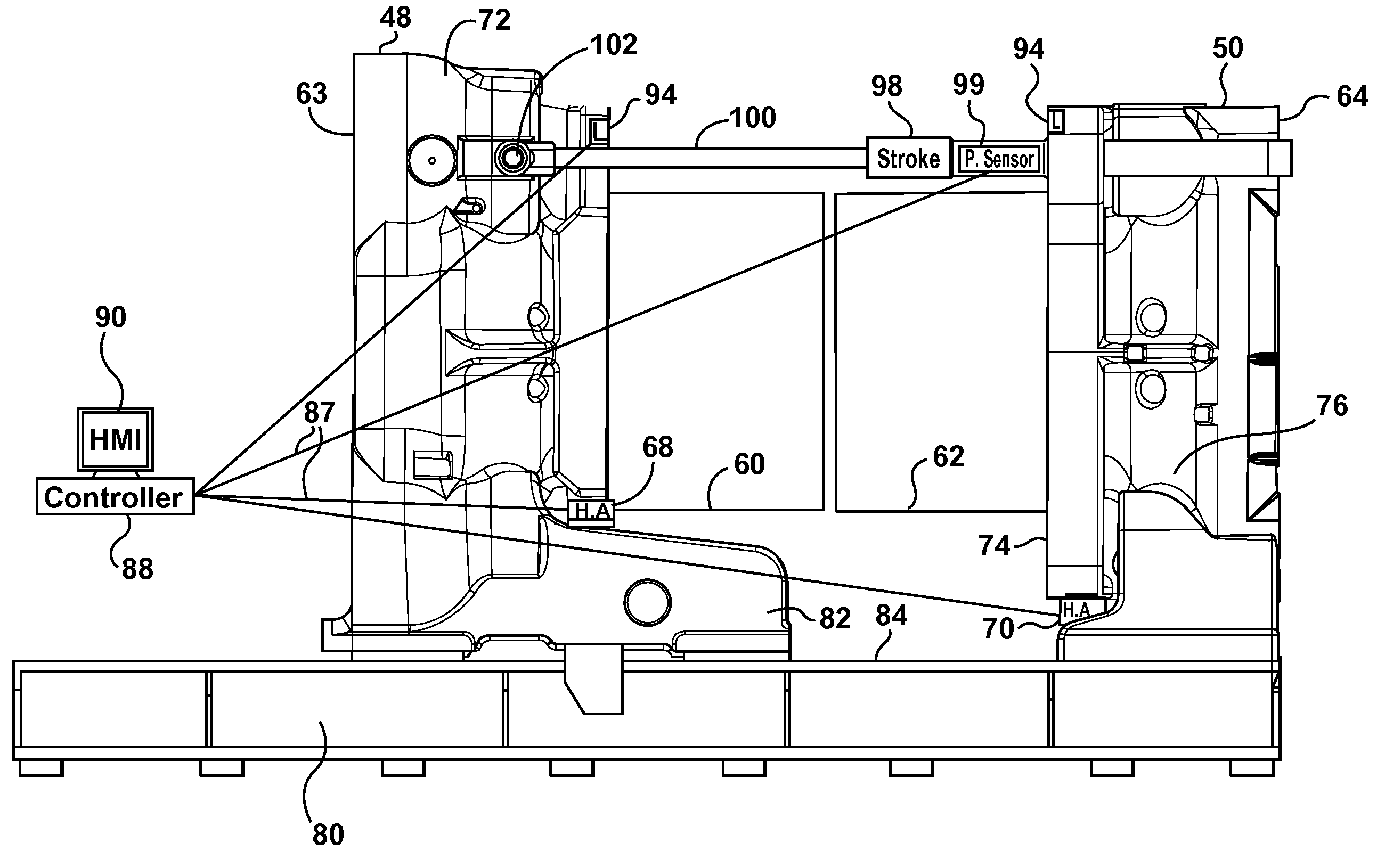
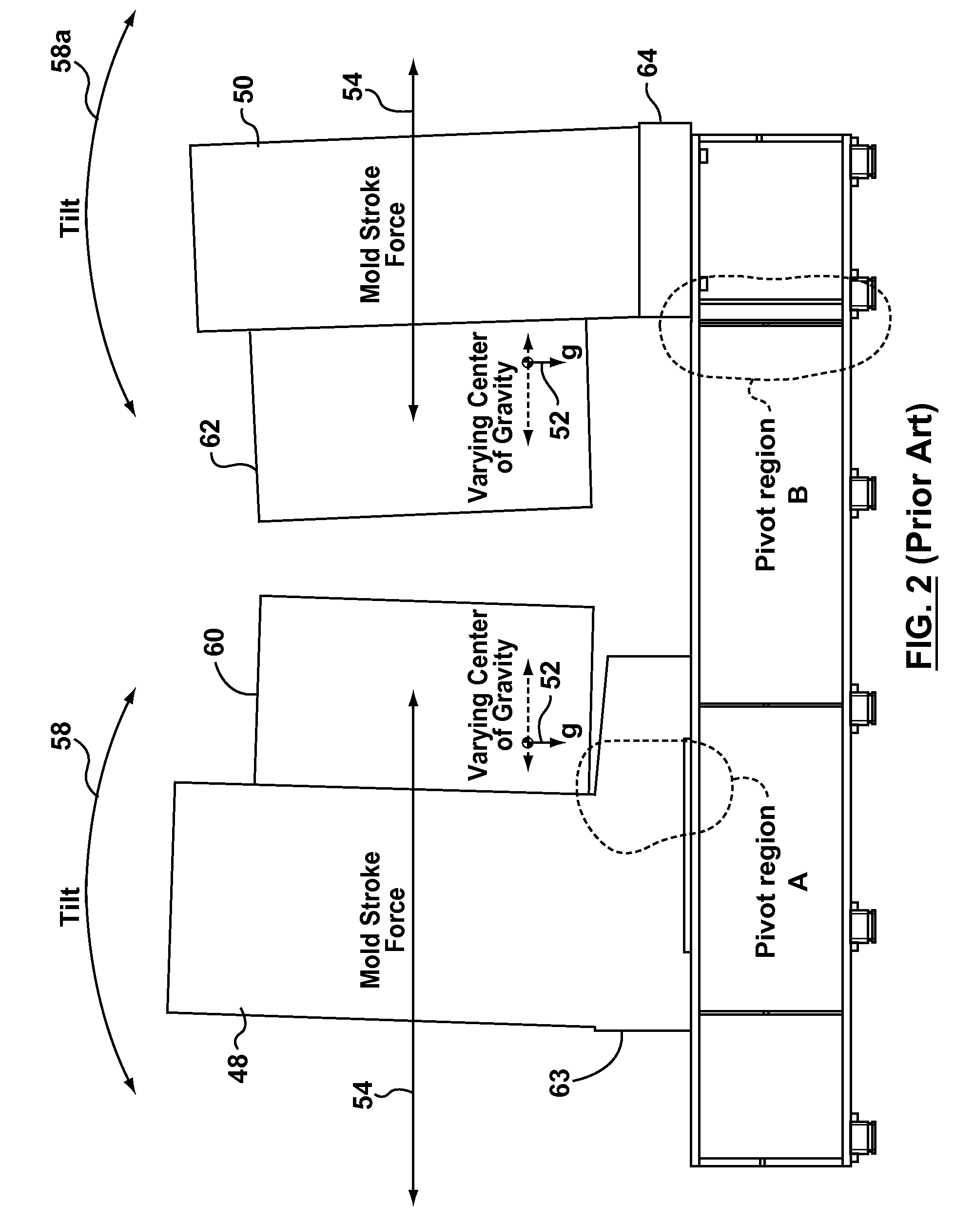
[0037]Since platen tilting is particularly problematic with heavy molds with large overhanging regions (extending outwardly of the mold mounting faces), the molding machine can be considered (for reasons of explanation only and without limitation) to be a large tonnage molding machine supporting a mold that is in excess of 20 tons and more typically a mold having a mass in the region of between about 40 tons to 100 tons.

[0038]FIG. 1 is shown for exemplary purposes as a two-platen system, although it could be a three-platen system or a molding system containing a centre-sec...


PUM

PropertyMeasurementUnit
massaaaaaaaaaa
massaaaaaaaaaa
centre of gravityaaaaaaaaaa

Abstract

FIG. 3 illustrates a system in which gravitation and inertial effects on platen verticality and sagging are compensated by an anti-tilt actuator (68, 70). Specifically, and particularly with the location of a heavy weight mold half (60, 62) on a platen (48, 50), platen tilting (58) and front face sagging occurs as a consequence of at least one of: i) the overhanging mass of the mold half; ii) inertia effects caused by stroking of the platen. A hydraulic actuator (68, 70) secured beneath the platen is either set to offset only gravitationally-related sagging of the mold half (60, 62) by providing a compensating upward force (relative to a stable clamp base 80), or otherwise its upward force can be dynamically adjusted also to compensate for swaying or tilting of the mold-platen assembly caused by stroke cylinder (98) operation and related inertia / momentum effects. Preferably, a level sensor (94) measures and communicates a degree of horizontalness / verticality of the platen (48, 50) to a machine controller (88) which, in turn, generates a control signal (87) to cause variation in cylinder pressure in the anti-tilt actuator (68, 70), thereby achieving substantially continuous alignment between the mold halves (60, 62) and reduced component wear.

Description

FIELD OF THE INVENTION[0001]This invention relates, in general, to a platen onto which is mounted (within a molding machine environment) a mold. More particularly, but not exclusively, the present invention relates to a mechanism for platen alignment and orientation and to an ability to compensate for platen tilting caused by different mold masses and / or the application of dynamically varying mold stroke forces during clamping cycles.SUMMARY OF THE PRIOR ART[0002]During the course of the life of an injection molding machine, it is not unreasonable to assume that the machine will be used to produce many different products from multiple different molds having different mold masses. Each mold contains a hot half and a cold half, with these complementary mold halves installed opposite each other on either a stationary platen and a moving platen. In order to permit the effective molding of parts, it is necessary for these mold halves to be securely attached to the platens and accurately ...

Claims


Application Information

Patent Timeline
Patent Type & Authority Applications(United States)
IPC IPC(8): B29C45/76B28B17/00B29C48/92
CPCB29C45/1744B29C45/76B29C2945/76227B29C2945/76387B29C2945/76391B29C2945/76394Y10S425/01B29C2945/76705B29C2945/76866B29C2945/76869B29C2945/76872B29C2945/76933B29C47/92B29C2945/76568
Inventor GLAESENER, PIERRELUIJS, RUUD
Owner HUSKY INJECTION MOLDING SYST LTD
Why Eureka
Try Eureka