Guard and Control Apparatus for Safe Operation of a Rotary Cutter

Active Publication Date: 2018-09-20
G A W INC
View PDF4 Cites 0 Cited by
  • Summary
  • Abstract
  • Description
  • Claims
  • Application Information

AI Technical Summary

Benefits of technology

[0005]The present invention is directed to an improved guard and guard control apparatus for a rotary cutting power tool that gives the user greater control over the power tool, while keeping both hands of the user away from the cutting element in the event of a sudden kickback. The guard includes a retractable portion, and the guard control apparatus includes an auxiliary handle (that is, a secondary handle used to stabilize and help support the tool driver) fastened to the housing of the power tool, a spring-biased lever, and latching elements mounted in the auxiliary handle for selectively and temporarily latching the retractable portion of the guard in a retracted position to enable plunge and other complex cutting operations. When the user releases the spring-biased lever on the auxiliary handle, the retractable portion of the guard is released and returns to its default or un-retracted position.
[0006]Maintaining the retractable portion of the guard in the retracted position during operation of the power tool in this manner occupies both hands of the user. This not only helps the user stabilize and accurately control the power

Problems solved by technology

Even when used by skilled operators, such cutting tools can be hazardous due to flying debris and a phenomenon known as kick-back, where the business end of the power tool suddenly jumps aw

Method used


Image

  • Guard and Control Apparatus for Safe Operation of a Rotary Cutter
  • Guard and Control Apparatus for Safe Operation of a Rotary Cutter
  • Guard and Control Apparatus for Safe Operation of a Rotary Cutter

Examples


Example

[0025]FIGS. 1-4 depict a first embodiment in which the rotary orientation of the guard mechanism 26 with respect to the spindle 19 can be locked in any desired orientation. On the other hand, FIGS. 5-7 depict a second embodiment in which the rotary orientation of the guard mechanism 26 can be locked in one of several preset orientations. In either case, the selected rotary alignment does not affect the operation of the guard latch mechanism 50.

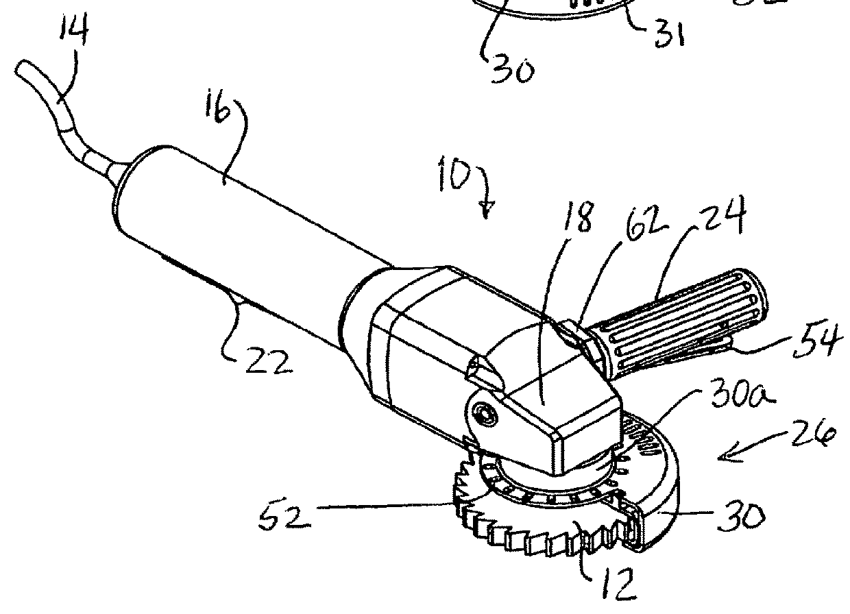
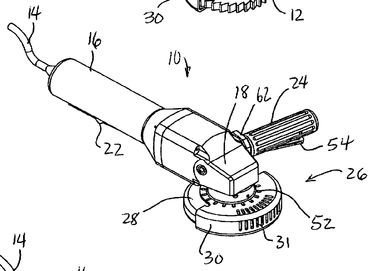
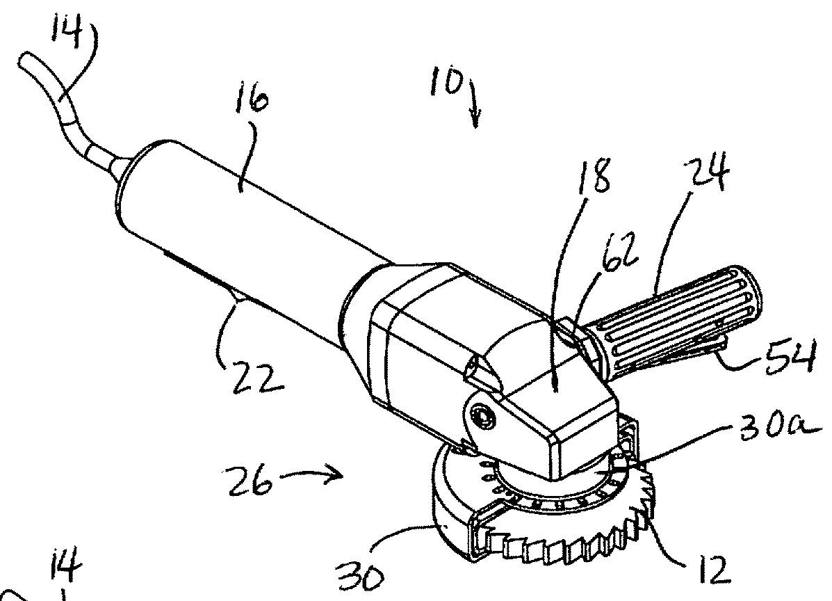
[0026]Referring to the first embodiment, and particularly to FIGS. 2A-2B, the fixed and retractable guard portions 28, 30 have coaxial tubular collars 28a, 30a that axially overlap and fit over the spindle 19. In this embodiment, the rotary orientation of the fixed guard portion 28 can be locked in any desired position, and the locking mechanism for securing the fixed guard portion 28 to the spindle 19 is implemented with a pair of set screws 36 threaded into the collar 28a. When sufficiently tightened, the set screws 36 forcibly engage the sp...

Example

[0033]Turning now to FIGS. 5-7 and second embodiment of this invention, the elements that correspond but differ from those of the first embodiment are designated by primed like reference numerals. For example, the guard mechanism is generally designated by the reference numeral 26′, and the fixed and retractable guard portions are designated by the reference numerals 28′ and 30′, respectively. As mentioned above, the main functional difference between the two embodiments is that the rotary orientation of the guard mechanism 26′ can be locked in one of limited number of preset positions. While this limits the way the guard mechanism 26′ can be used, it allows a locking mechanism that is more robust than the set screws 36 of the first embodiment, and allows the user to make deeper plunge cuts with the cutting element 12. Another difference, albeit incidental, is that the guard mechanism 26′ of the second embodiment is configured so that its retractable guard portion 30′ retracts throu...


PUM

PropertyMeasurementUnit
Forceaaaaaaaaaa

Abstract

A power tool that drives rotary cutting element has a retractable guard for the cutting element, and a guard control apparatus allows a user to maintain the guard in a retracted position during operation of the power tool. The guard control apparatus includes an auxiliary handle fastened to the housing of the power tool, and latching elements linked to a spring-biased lever mounted in the auxiliary handle for selectively and temporarily retaining the retractable portion of the guard in a retracted position to enable plunge and other complex cutting operations. An alignment ring is selectively engaged by a user-manipulated alignment pin to rotationally lock the guard in one of a preset number of rotary orientations.

Description

RELATED APPLICATIONS[0001]This application is a continuation-in-part of pending non-provisional U.S. patent application Ser. No. 15 / 648,562 filed Jul. 13, 2017.TECHNICAL FIELD[0002]This invention relates to pneumatic or electric rotary cutter power tools, and more particularly to a guard and guard control apparatus for improving the safety of workers using such power tools.BACKGROUND OF THE INVENTION[0003]Rotary cutter power tools of the pneumatic or electric variety are used in many industrial applications that require a worker to manually cut heavy material such as plate steel or aluminum. The cutting element can be an abrasive disk or a toothed wheel, depending on the application. Even when used by skilled operators, such cutting tools can be hazardous due to flying debris and a phenomenon known as kick-back, where the business end of the power tool suddenly jumps away from the workpiece. Safety guards that partially enclose the cutting element can reduce the risk of user injury ...

Claims


Application Information

Patent Timeline
IPC IPC(8): B27G19/04
CPCB27G19/04B24B23/028B24B55/052B23D45/16
Inventor ARTHUR, ROBERTRUSSELL, NICHOLAS J.
Owner G A W INC
Why Eureka
Try Eureka