Display device

A display device and display panel technology, applied in nonlinear optics, instruments, optics, etc., can solve the problems of reducing the brightness of 2D images, wasting light, and not being able to penetrate all light, and achieve the effect of improving the brightness effect

Active Publication Date: 2013-10-23
KUSN INFOVISION OPTOELECTRONICS
View PDF2 Cites 0 Cited by
  • Summary
  • Abstract
  • Description
  • Claims
  • Application Information

AI Technical Summary

Problems solved by technology

[0010] However, for a display device in which the traditional 2D / 3D display mode can be converted to each other, when the 2D display mode is performed, the liquid crystal lens 3 has a certain degree of influence on the transmittance of the light emitted by the backlight 1, and, Due to the existence of the black matrix BM in the display panel 2, the light emitted from the backlight 1 cannot completely penetrate the display panel 2, resulting in the waste of part of the light emitted by the backlight 1, thereby reducing the 2D image perceived by the observer. brightness

Method used


Image

  • Display device
  • Display device
  • Display device

Examples


no. 1 example

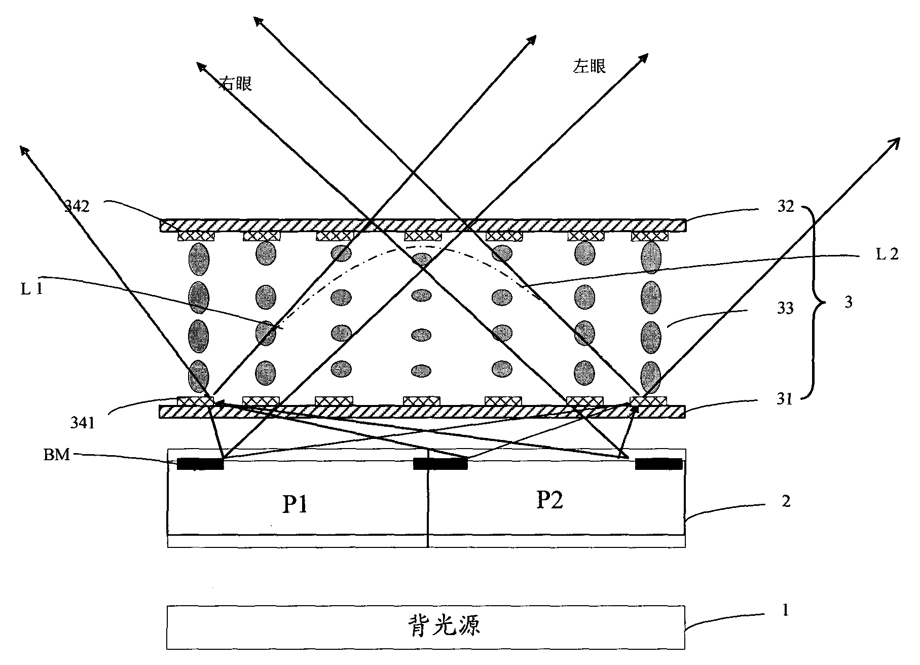
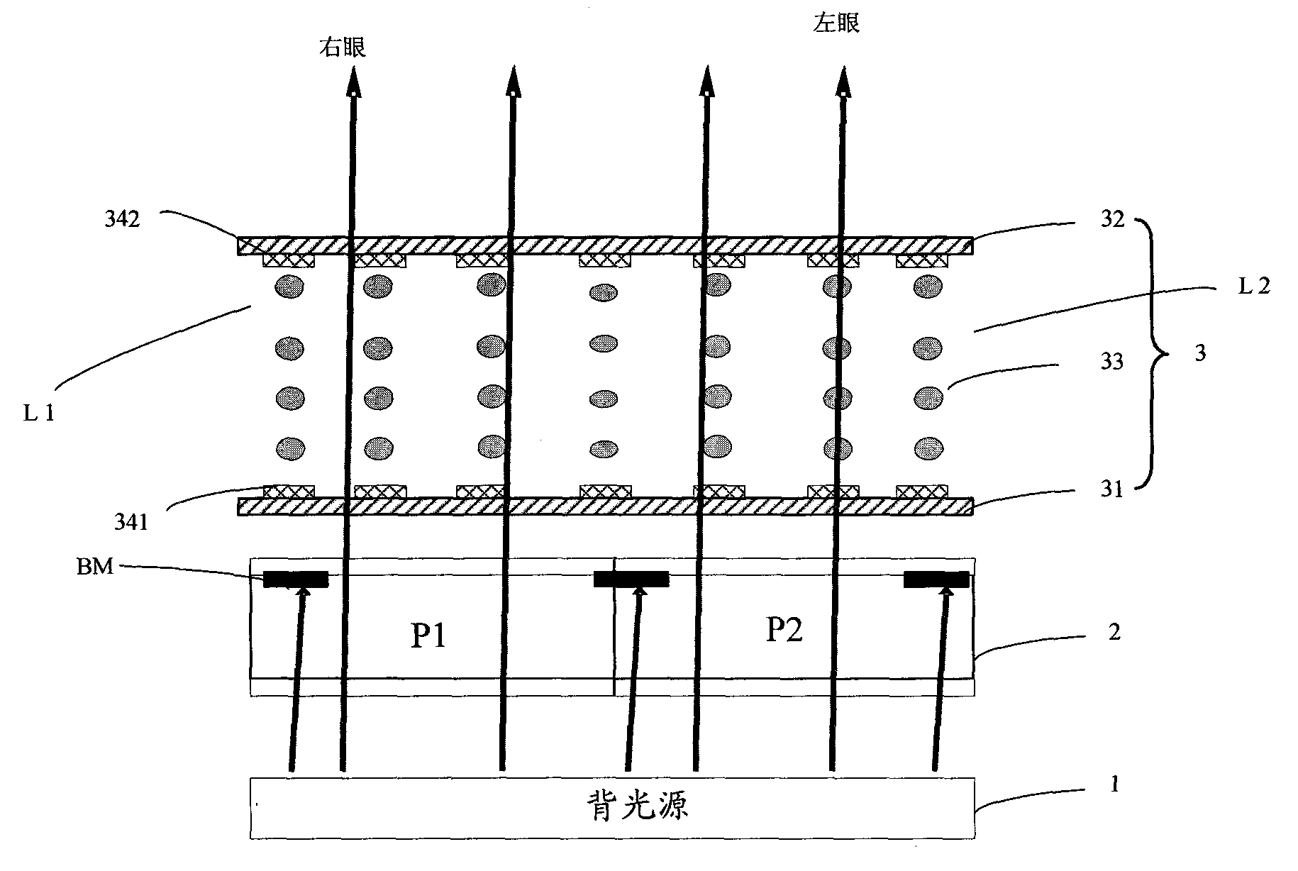
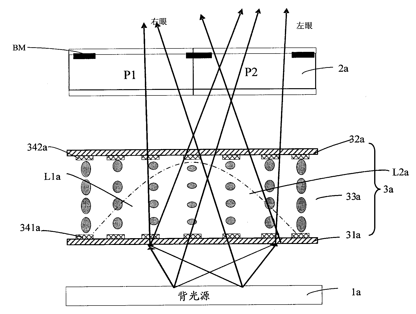
[0033] In the display device of the first embodiment of the present invention, the principle of forming a stereoscopic image is as follows: Figure 2a with 2b as shown, Figure 2a with 2b What is shown is a display device in which 3D / 2D display modes can be converted to each other, wherein, Figure 2a Shown is a schematic diagram of the principle of 3D display by the display device of the first embodiment, Figure 2b Shown is a schematic diagram of the principle of 2D display by the display device of this embodiment. First, refer to Figure 2a , the display device includes in turn: a backlight source 1a for providing light; a liquid crystal lens 3a; and a display panel 2a, which includes a plurality of pixel units each composed of a first pixel P1 and a second pixel P2, further , the display panel 2a also includes a black matrix (BM) for light shielding. In more detail, the liquid crystal lens 3a includes a first substrate 31a, a second substrate 32a opposite to the firs...

no. 2 example

[0044]In the display device of the second embodiment of the present invention, the principle of forming a stereoscopic image is as follows: Figure 3a with 3b as shown, Figure 3a It is a schematic diagram of the principle of 3D display by the display device according to the second embodiment of the present invention, Figure 3b Shown is a schematic diagram of the principle of 2D display by the display device of this embodiment. In the second embodiment, the liquid crystal lens 3b is also arranged between the backlight source 1b and the display panel 2b. The difference from the first embodiment is that the structure of the liquid crystal lens 3b in the display device of this embodiment is different. Such as Figure 3a As shown, the liquid crystal lens 3b of this embodiment sequentially includes: a first substrate 31b, a second substrate 32b opposite to the first substrate 31b, and a liquid crystal layer sealed between the first and second substrates 31b, 32b 33b, the liqui...


PUM


Abstract

The invention discloses a display device, which comprises a display panel, a liquid crystal lens and a backlight source; the display panel comprises a plurality of pixel units, and each pixel unit comprises a first pixel and a second pixel; the liquid crystal lens comprises a first substrate and a second substrate which are opposite, and a liquid crystal layer sealed between the first and second substrates; the liquid crystal lens also comprises an electrode; the backlight source is used for supplying rays to the display panel; the display panel, the liquid crystal lens and the backlight source are sequentially arranged; and the arrangement state of liquid crystal molecules on each liquid crystal lens unit is changed according to the voltage applied to the electrode, so that the focal length of the each liquid crystal lens unit is changed. The display device can be compatible with 2D / 3D display modes, and can improve the utilization rate of light in the 2D display mode.

Description

technical field [0001] The invention relates to the field of liquid crystal display, in particular to a display device. Background technique [0002] With the increase in size and resolution of television sets, in order to provide viewers with more realistic images, high-definition television (HDTV: High Definition Television) technology has become a goal that people are constantly pursuing. [0003] As we all know, the real world is a three-dimensional world, and people's three-dimensional visual effect mainly depends on two human eyes, that is, the surrounding environment seen by human eyes actually has a slight direction deviation. The deviations produced by the distance between the two eyes of people or the pupils of the two eyes are different. The average interpupillary distance of an adult is about 65 mm, which makes two images with a slight difference in viewing angle formed on the human retina, and then through further fusion of the human brain, the observer can per...

Claims


Application Information

Patent Timeline
Patent Type & Authority Patents(China)
IPC IPC(8): G02F1/29
Inventor 钟德镇李永谦戴文君廖家德
Owner KUSN INFOVISION OPTOELECTRONICS
Why Eureka
Try Eureka