Gas collection method and apparatus thereof

A technology of gas and collector, which is applied in the field of gas collection and gas collection devices, and can solve the problem of difficult recovery of gas components

Inactive Publication Date: 2005-06-29
KK TOSHIBA
View PDF1 Cites 0 Cited by
  • Summary
  • Abstract
  • Description
  • Claims
  • Application Information

AI Technical Summary

Problems solved by technology

At this time, however, large-scale equipment is required for the preparation of humid gas, and materials with high corrosion resistance must be used for the gas collection device
Also, due to the difference between the gas temperature and the HDD temperature, condensation tends to occur, which makes the collected gas fraction difficult to recover

Method used


Image

  • Gas collection method and apparatus thereof
  • Gas collection method and apparatus thereof
  • Gas collection method and apparatus thereof

Examples


Embodiment Construction

[0018] Referring now to the accompanying drawings, a gas collection method and a gas collection device according to embodiments of the present invention will be described in detail.

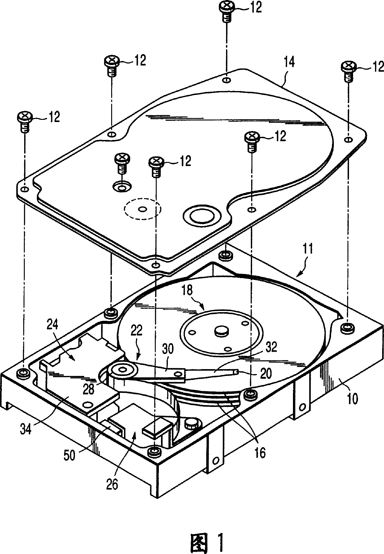
[0019] First, an example of an HDD to be checked will be described. As shown in FIG. 1 , the HDD includes a casing 11 of a substantially airtight structure, which includes a casing main body 10 and a top cover 14 . The housing body 10 is in the shape of a rectangular box with an open top, and the top cover 14 is screwed onto the housing body 10 with several screws 12 to close the open top of the housing body 10 .

[0020] Arranged in the case main body 10 are, for example, two magnetic disks 16 each serving as a magnetic recording medium; a spindle motor 18 for supporting and rotating these magnetic disks 16; Reading / writing of information; Carriage assembly 22, it supports these magnetic heads 20; Voice coil motor (VCM) 24, in order to rotate and position carriage assembly 22; And board assembl...


PUM


Abstract

The disc device (50) has an open inner structure, and it and the collector liquid (46) are placed in the hermetically sealed collection container (40) and heated to a certain collection temperature by the heating mechanism to allow the gas to flow from the disc generated in the device, and evaporate the collector liquid. Vapors of the collector liquid contact the tray means and collect gas generated from the tray means, then the collection container is cooled to liquefy the vapors that have collected gas generated from the tray means.

Description

technical field [0001] The invention relates to a gas collection method and a gas collection device for collecting gas generated during the operation of a disk device, in particular to a gas collection method and a gas collection device for quantitatively calculating the corrosive gas generated in the disk device. Background technique [0002] Generally, a disk device such as a hard disk drive (hereinafter referred to as "HDD") includes a magnetic disk, a spindle motor for rotating the magnetic disk, a magnetic head for reading / writing data relative to the magnetic disk, a head suspension assembly for supporting and moving the magnetic head, And the VCM (Voice Coil Motor) for the drive head suspension assembly. These components of the disk device are arranged in a casing of a substantially airtight structure. If an airtight enclosure is used, the floating operation of the magnetic head relative to the magnetic disk during read / write operations can be stabilized. It also pr...

Claims


Application Information

Patent Timeline
Patent Type & Authority Patents(China)
IPC IPC(8): G11B33/14B01D53/00G01N1/02
CPCB01D53/002
Inventor 富冈由喜
Owner KK TOSHIBA
Why Eureka
Try Eureka